High precision follower device with zero power, zero noise slew enhancement circuit

a follower device and zero power technology, applied in the direction of amplifiers, amplifiers with semiconductor devices only, amplifiers with semiconductor devices, etc., to achieve the effect of reducing noise, reducing power output, and increasing the slew rate of followers

Inactive Publication Date: 2010-08-26
ANALOG DEVICES INC
View PDF1 Cites 15 Cited by
  • Summary
  • Abstract
  • Description
  • Claims
  • Application Information

AI Technical Summary

Benefits of technology

[0008]To address the above limitations of the prior art, the present invention provides a configuration of an amplifier circuit where a follower device has been coupled with a slew enhancement circuit in order to increase the slew rate of the follower while minimizing the power output. The present invention is also advantageous in that the configuration of the present invention allows for the reduction of noise and quick settling of the output voltage.
[0011]The slew enhancement circuit contains a three-terminal transistor that is coupled to the follower and is turned on when the drain current of the follower device drops below a threshold set by the designer. Output current from the three-terminal transistor is sent through the current amplifier, where a significant current gain can be achieved. The current output from the current amplifier can be sent to the source of the follower (the emitter if a BJT is used), which allows for the voltage output of the source follower to settle quickly. The current amplifier is normally in the off-stage and only turns on when the follower device's current is too low. Because the current amplifier circuitry is in the off-stage in the quiescent state, no noise is produced at the output by the slew enhancement circuit.
[0013]The invention makes use of devices that are used to achieve precision, to facilitate the natural engagement of the slew enhancement when the circuit requires it, so that high speed and precision are complimentary features.

Problems solved by technology

At low power, the quiescent current alone may not be enough to settle the output voltage fast enough and thus a multiplication of the current is needed.

Method used


Image

  • High precision follower device with zero power, zero noise slew enhancement circuit
  • High precision follower device with zero power, zero noise slew enhancement circuit
  • High precision follower device with zero power, zero noise slew enhancement circuit

Examples


Embodiment Construction

[0017]The subject invention will now be described in detail for specific preferred embodiments of the invention, it being understood that these embodiments are intended only as illustrative examples and the invention is not to be limited thereto.

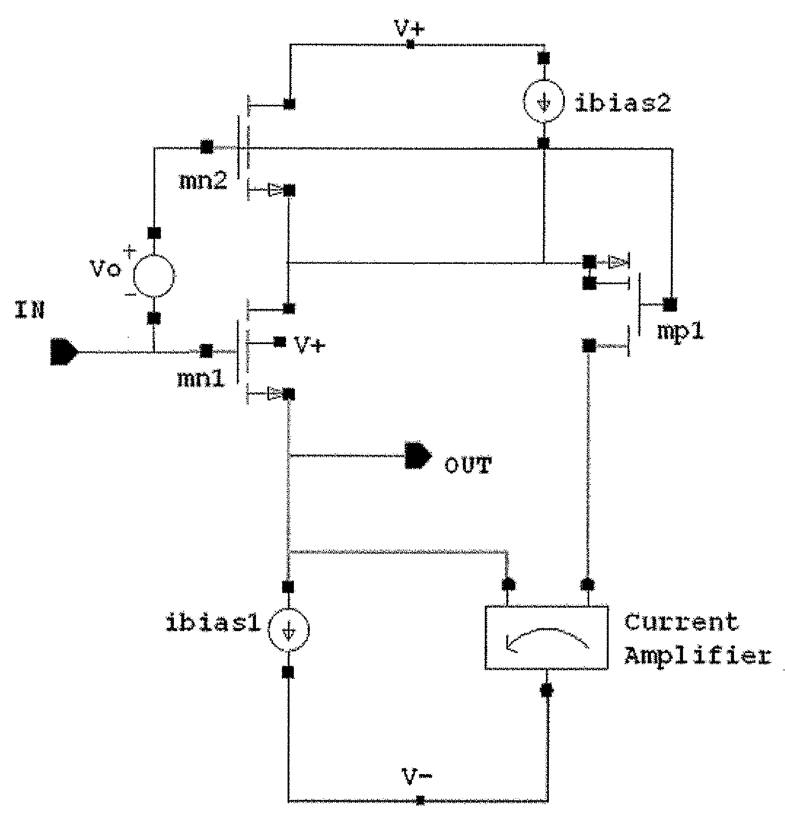
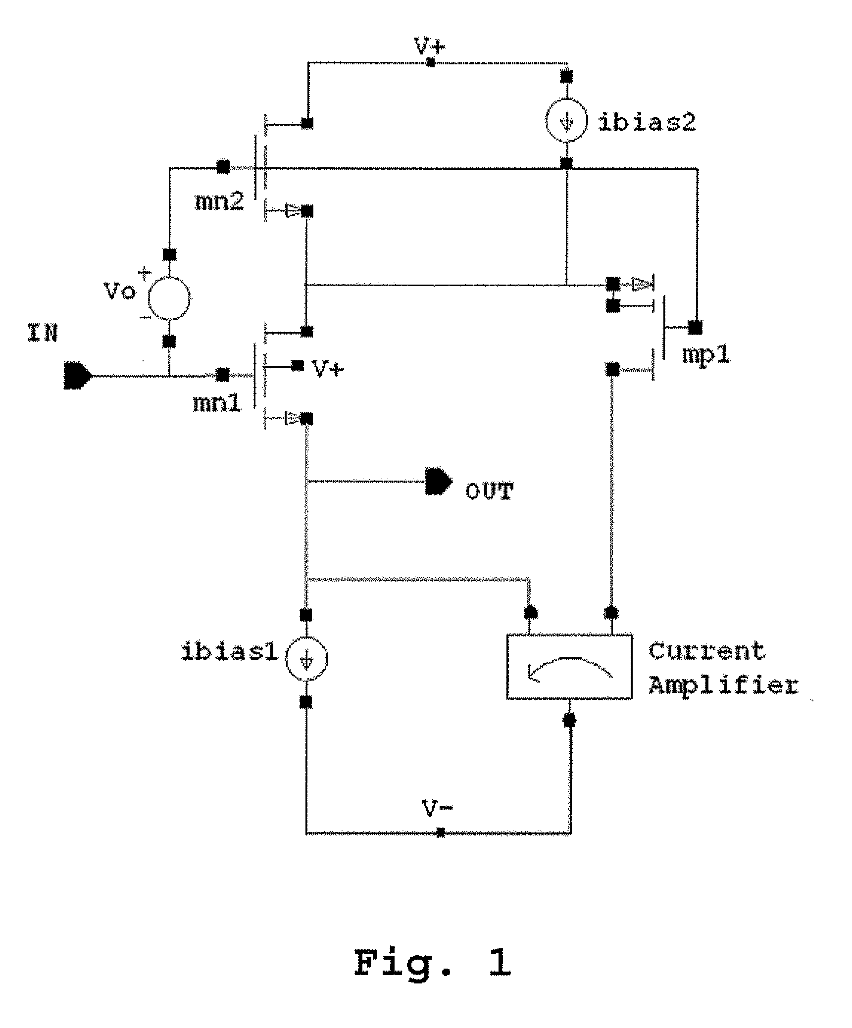
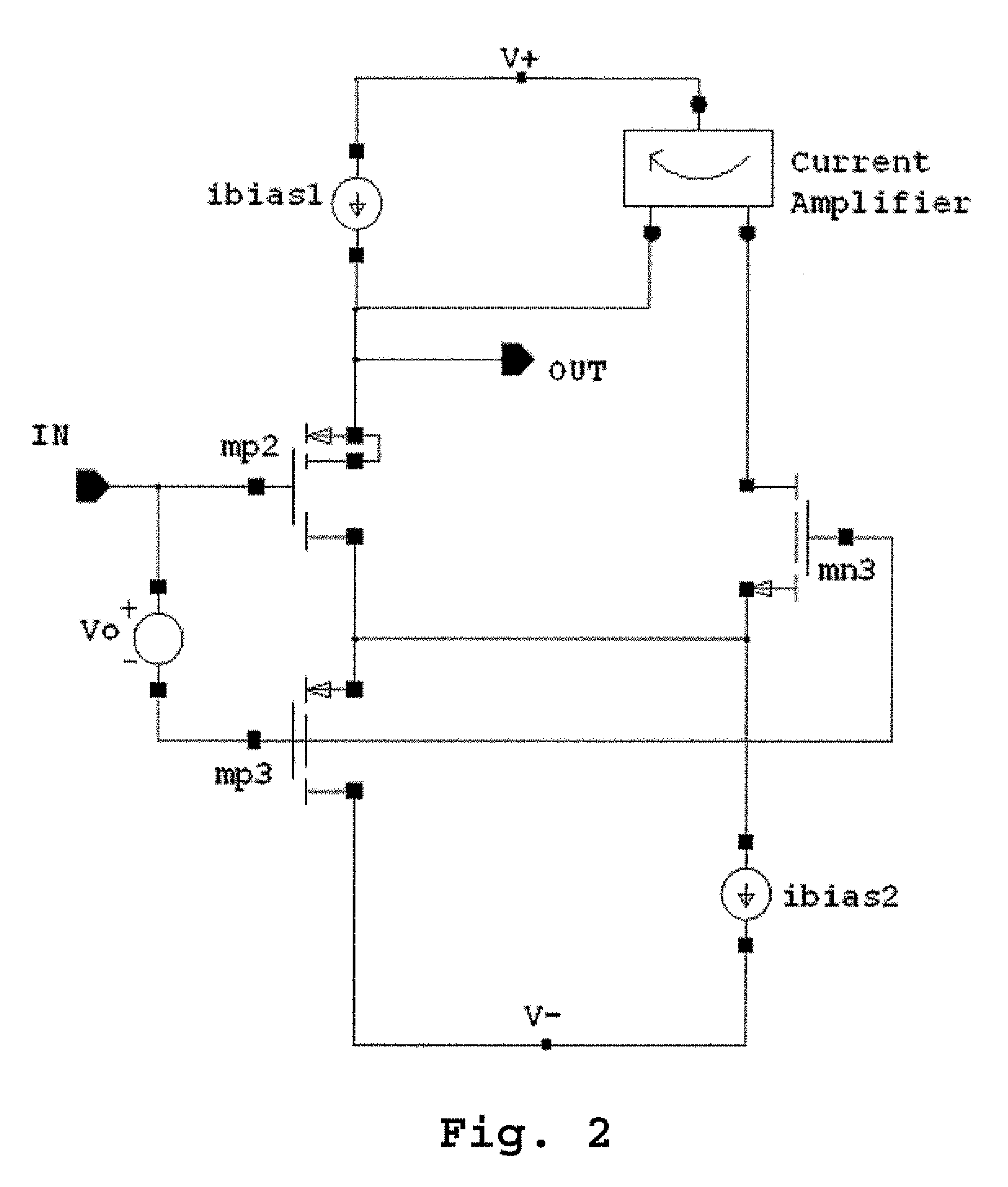
[0018]In the preferred embodiment, described herein, the follower device is selected to be source follower, which is shown in FIGS. 1 and 2. It should be understood that the present invention alternatively applies to configurations where an emitter follower is implemented or for use with any device where a linear correlation between input and output is desired.

[0019]FIG. 1 shows an embodiment of the present invention, with an n-type source follower connected to a slew enhancement circuit. The source follower, designated as mn1 in FIG. 1, can also be selected to be a p-type source follower, as is shown by mp2 in FIG. 2. The difference between an n-type follower and a p-type follower is the doping of the follower device, with an n-type followe...


PUM


Abstract

A high performance follower device coupled with a slew enhancement circuit includes an amplifier circuit containing a follower device connected to a three-terminal device, whereupon current drawn through the three-terminal device is amplified through a current amplifier and sent to the source terminal of the follower device to stabilize the output voltage when the input signal is changed rapidly or if the output voltage is disturbed by a changing output load. The presence of a cascode device also allows for the bootstrapping of the follower device.

Description

FIELD OF THE INVENTION[0001]The present invention particularly relates to the design of a slew enhancement circuit that stabilizes the output voltage of a follower device. The present invention further relates to a method of increasing the slew rate in a follower device.BACKGROUND INFORMATION[0002]In the design of precision circuits, the immunity of a circuit to the effects of non-linearity, noise, and common mode voltages tends to be a priority. In slower applications that require low power, these concerns can be alleviated easily. In many applications however, requirements for high speed and high precision are necessary and achieving this while maintaining low power is not readily obvious. This makes the implementation of devices such as a simple source follower more complex especially as one attempts to achieve a low power output.[0003]Two types of common follower devices are source followers and emitter followers. A source follower is a configuration of a field-effect transistor...

Claims


Application Information

Patent Timeline
IPC IPC(8): H03F3/16
CPCH03F2203/5031H03F3/505
Inventor COONEY, PADRAIG
Owner ANALOG DEVICES INC
Why Eureka
Try Eureka