
Detecting Light Load Conditions and Improving Light Load Efficiency in a Switching Power Converter

a technology of switching power converter and light load, which is applied in the direction of electric variable regulation, process and machine control, instruments, etc., can solve the problems of current conduction loss or switching loss in the power switch, power loss, conduction loss, etc., to reduce the switching frequency, the effect of reducing the switching loss in the power converter

Active Publication Date: 2010-08-19
DIALOG SEMICONDUCTOR INC
View PDF4 Cites 138 Cited by
  • Summary
  • Abstract
  • Description
  • Claims
  • Application Information

AI Technical Summary

Benefits of technology

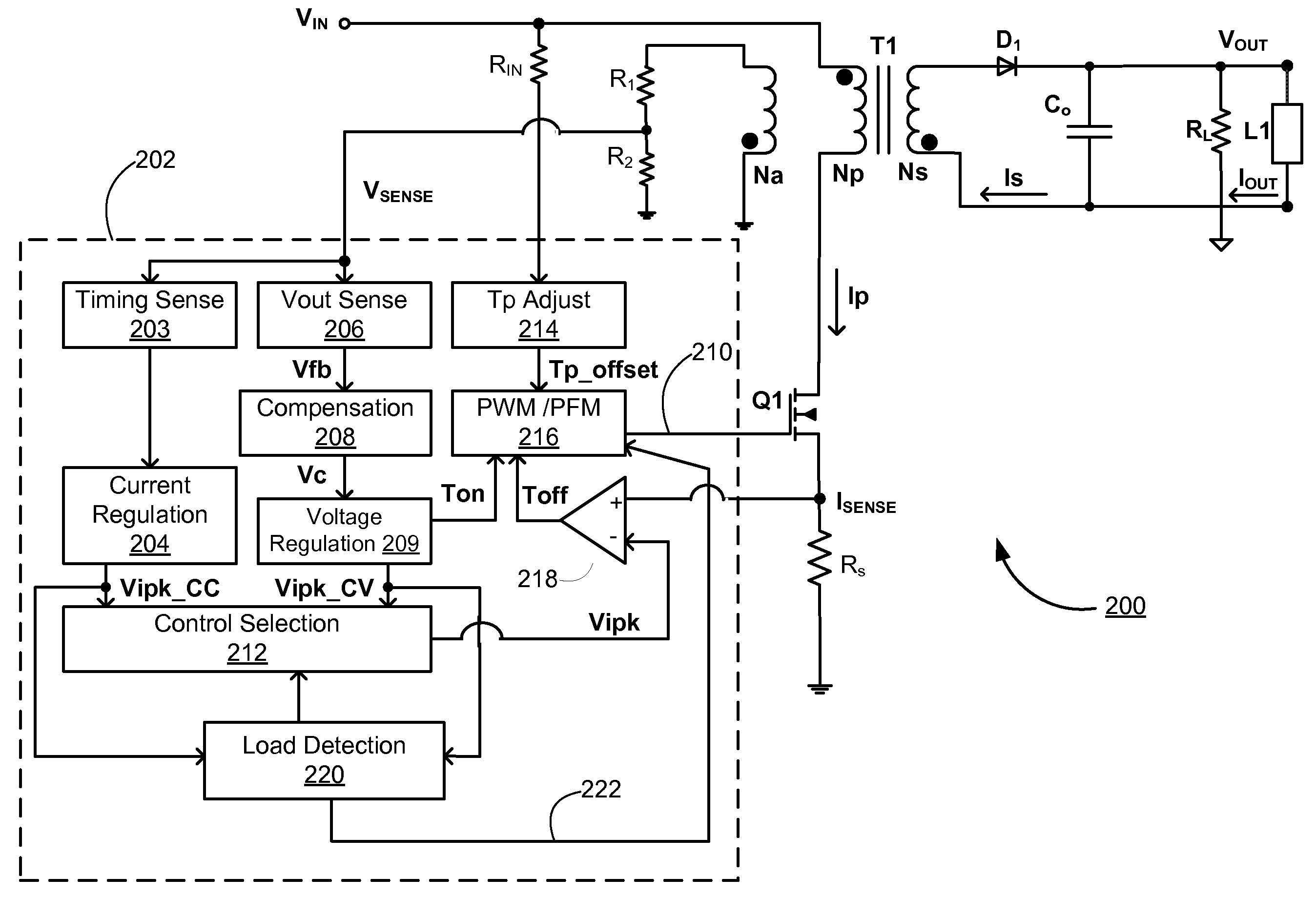
[0014]Once a low load condition is detected, the switching frequency of the switching power converter is reduced to a level that minimizes switching loss in the power converter. In addition, the switching power converter also reduces the switching frequency according to the sensed input line voltage. An offset is added to the switching period to reduce the switching frequency of the switching power converter, as the input line voltage is increased.
[0015]Using the ratio of the first peak current value for peak current switching in constant voltage regulation mode to the second peak current value for peak current switching in constant current regulation mode to detect low load conditions in the switching power converter has several advantages, including removing the sensitivities of low load detection caused by changes in the input line voltage, magnetizing inductance of the transformer in the switching power converter, and the switching frequency, and immunity to these changes brings more accurate detection of low load conditions. Also, since the switching frequency is further reduced when the input line voltage is increased, additional gains in efficiency can be achieved in the switching power converter of the present invention.

Problems solved by technology

In switched mode power supplies, power loss results from either current conduction loss or switching loss in the power switch.
Under heavy load conditions, current is high and thus conduction loss is the dominating factor.
However, under light load conditions, current is low and thus switching loss is the dominating factor.
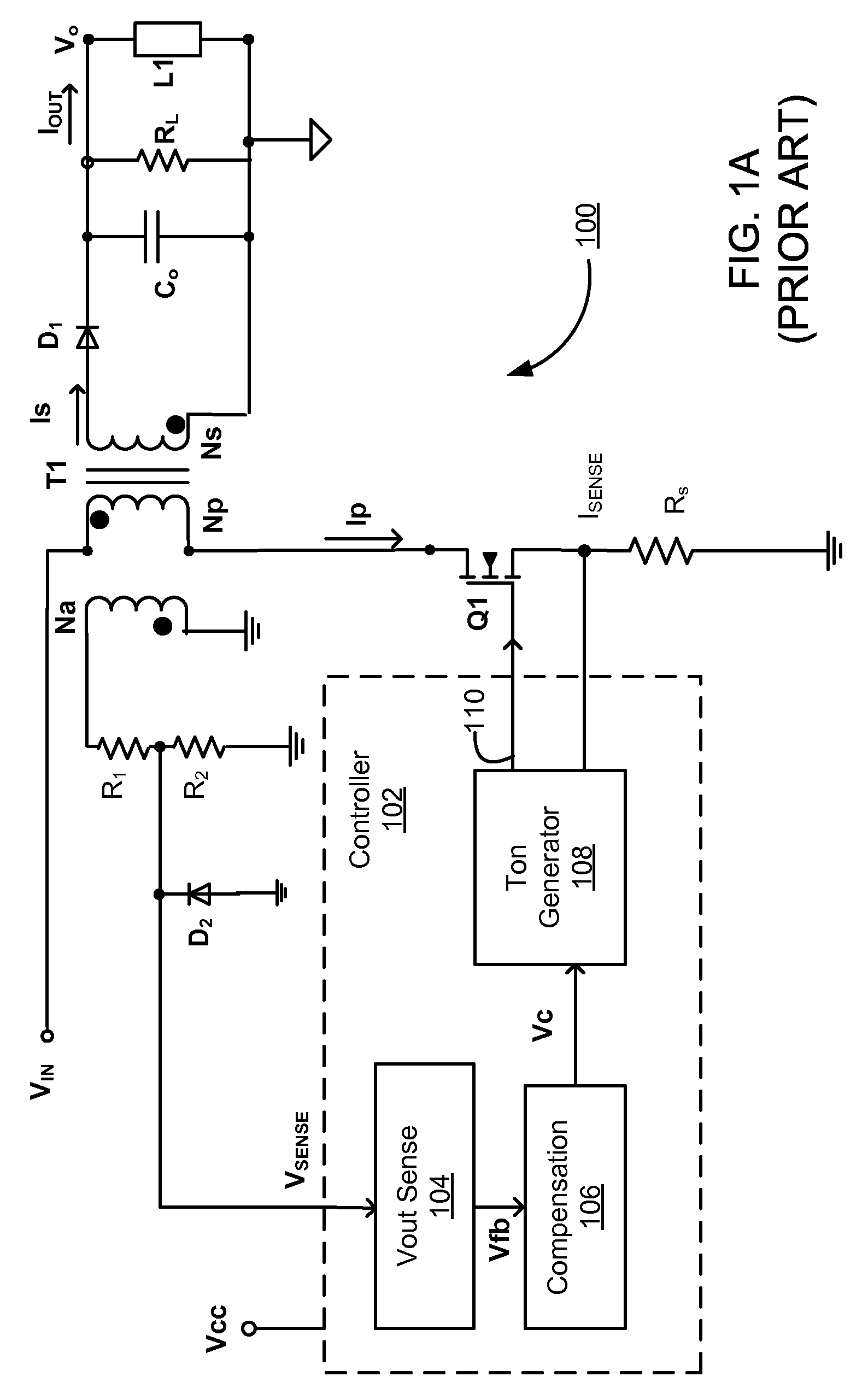
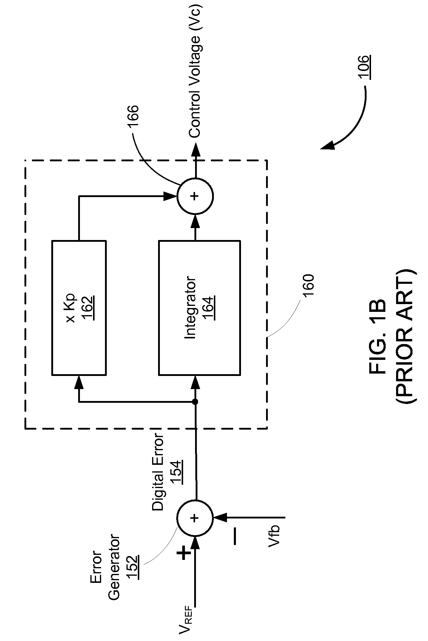
However, using the control voltage Vc to detect low load conditions may not be desirable or accurate, if the switching frequency of the switching power converter is not constant.
This is because the control voltage Vc does not always correctly identify light load conditions.
However, if there is large reduction of switching frequency fs over a short load range, higher Vc does not necessarily represents higher output power if the switching frequency changes.
Furthermore, when light load conditions are detected, conventional switching power supplies may lower the switching frequencies in the same manner without regard to the level of the input line voltage.
This may result in additional inefficiencies because at high input line voltages the switching loss is more significant than that at low input line voltages.

Method used


Image

  • Detecting Light Load Conditions and Improving Light Load Efficiency in a Switching Power Converter
  • Detecting Light Load Conditions and Improving Light Load Efficiency in a Switching Power Converter
  • Detecting Light Load Conditions and Improving Light Load Efficiency in a Switching Power Converter

Examples


Embodiment Construction

[0025]The Figures (FIG.) and the following description relate to preferred embodiments of the present invention by way of illustration only. It should be noted that from the following discussion, alternative embodiments of the structures and methods disclosed herein will be readily recognized as viable alternatives that may be employed without departing from the principles of the present invention.

[0026]Reference will now be made in detail to several embodiments of the present invention(s), examples of which are illustrated in the accompanying figures. It is noted that wherever practicable similar or like reference numbers may be used in the figures and may indicate similar or like functionality. The figures depict embodiments of the present invention for purposes of illustration only. One skilled in the art will readily recognize from the following description that alternative embodiments of the structures and methods illustrated herein may be employed without departing from the pr...


PUM


Abstract

A switching power converter detects low load conditions based on the ratio of a first peak current value for peak current switching in constant voltage regulation mode to a second peak current value for peak current switching in constant current regulation mode. The power supply load is considered to have a low load if the ratio is lower than a predetermined threshold. Once a low load condition is detected, the switching frequency of the switching power converter is reduced to a level that minimizes switching loss in the power converter. In addition, the switching power converter also adjusts the switching frequency according to the sensed input line voltage. An offset is added to the switching period to reduce the switching frequency of the switching power converter, as the input line voltage is increased.

Description

BACKGROUND OF THE INVENTION[0001]1. Field of the Invention[0002]The present invention relates to detecting light load conditions and improving light load efficiency in a switching power converter.[0003]2. Description of the Related Arts[0004]In switched mode power supplies, power loss results from either current conduction loss or switching loss in the power switch. Under heavy load conditions, current is high and thus conduction loss is the dominating factor. However, under light load conditions, current is low and thus switching loss is the dominating factor.[0005]A conventional practice for improving light load efficiency in switching power converters is to reduce the switching frequency under light load conditions. In order to reduce the switching frequency under light load conditions, it is necessary to first detect such light load conditions accurately. Conventional switching power converters typically use the output signal of a control loop compensator in the switching power ...

Claims


Application Information

Patent Timeline
Patent Type & Authority Applications(United States)
IPC IPC(8): H02M3/335
CPCH02M3/33523Y02B70/16H02M2001/0032H02M1/0032Y02B70/10
Inventor YAN, LIANGWANG, XIAOYANZHENG, JUNZHENG, JUNJIEPOON, CLARITA
Owner DIALOG SEMICONDUCTOR INC
Learn More