Synchronous rectification circuit with dead time regulation
- Summary
- Abstract
- Description
- Claims
- Application Information
AI Technical Summary
Benefits of technology
Problems solved by technology
Method used
Image

Examples
Embodiment Construction
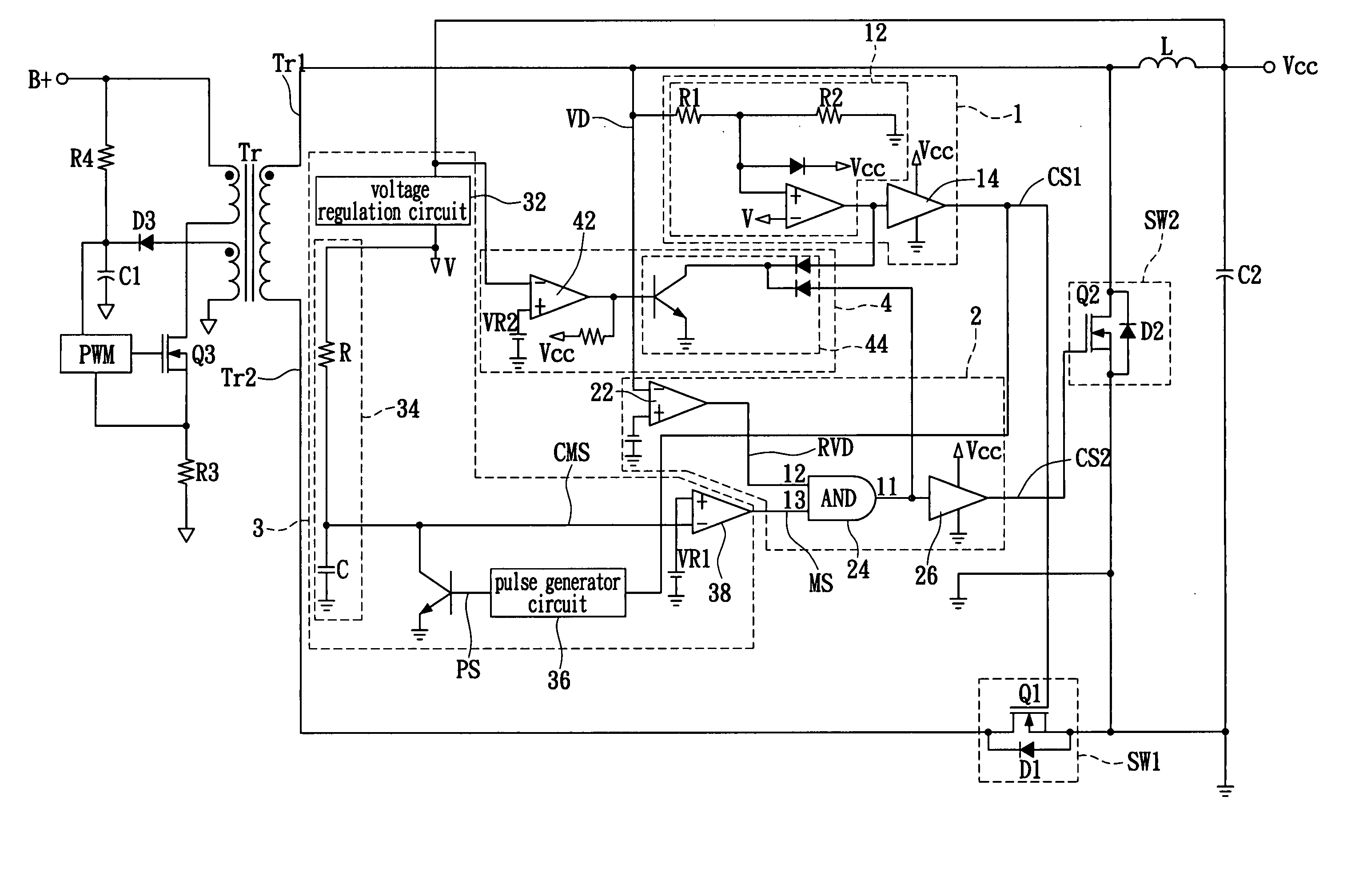
[0022] Referring to FIG. 3, a schematic circuit diagram of the forward power supply apparatus according to the present invention is shown. The circuit of the invention is connected to a secondary side of a transformer Tr, an inductor L, a first switch SW1 and a second switch SW2 and outputs a DC power Vcc. The circuit comprises a first switch control circuit 1, a second switch control circuit 2, a dead time regulation circuit 3 and a low voltage protection circuit 4. Two terminals are provided on the secondary side of the transformer Tr.
[0023] Referring to FIG. 3, the first switch control circuit 1 is connected to one terminal Tr1 on the secondary side of the transformer Tr through a waveform shaping circuit 12, which receives an input voltage VD and shapes the waveform of the input voltage VD to produce a first driving voltage VD1. Meanwhile, the first driving voltage VD1 is used for controlling operation of a first driver circuit 14 connected with the waveform shaping circuit 12....
PUM
 Abstract
Description
Claims
Application Information
 - R&D
- Intellectual Property
- Life Sciences
- Materials
- Tech Scout
- Unparalleled Data Quality
- Higher Quality Content
- 60% Fewer Hallucinations
Browse by: Latest US Patents, China's latest patents, Technical Efficacy Thesaurus, Application Domain, Technology Topic, Popular Technical Reports.
© 2025 PatSnap. All rights reserved.Legal|Privacy policy|Modern Slavery Act Transparency Statement|Sitemap|About US| Contact US: help@patsnap.com