
Cutting tool, method of forming cutting tool, and method of manufacturing cutting tool

a cutting tool and manufacturing technology, applied in the direction of manufacturing tools, shaping cutters, tool workpiece connection, etc., can solve the problems of lapsed machining time and wear of cutting edges, and achieve the effect of constant cross-section area of cutting edge portions, constant cutting resistance and extended cutting tip li

Inactive Publication Date: 2010-08-12
JTEKT CORP
View PDF16 Cites 3 Cited by
  • Summary
  • Abstract
  • Description
  • Claims
  • Application Information

AI Technical Summary

Benefits of technology

The present invention relates to a cutting tip used in cutting machines such as lathe, milling machine or the like. The technical effect of the invention is to prevent wear and chipping of the cutting edge, which can occur quickly in a relatively short period of time, by improving the materials used for the cutting tip and the construction of the cutting tip. The invention provides a cutting tip with a high-hardness material taking a thin plate shape and a support portion supporting the cutting edge portion on a reverse side of a rake face, which prevents wear and chipping of the cutting edge. The cutting tip can be secured to a cutting tool body or detachably secured, and can be machined to shape its edge. The invention also includes a method for improving the construction of the cutting tip by removing the extreme end face of the support portion.

Problems solved by technology

Generally, in cutting tips used in cutting machines, many of those use a cemented carbide increased in toughness and hardness as the material for the cutting tips, and with the details in operation taken into consideration, it is unavoidable that the cutting edges are worn away with lapse of machining time.
Further, there arises a problem that after being worn away, the cutting tips get the edge shapes changed to increase cutting resistance due to an increase of a contact area with a workpiece and that defects such as chipping occur in due course thereby to reach the end of the service life in a relatively short period of time.

Method used


Image

  • Cutting tool, method of forming cutting tool, and method of manufacturing cutting tool
  • Cutting tool, method of forming cutting tool, and method of manufacturing cutting tool
  • Cutting tool, method of forming cutting tool, and method of manufacturing cutting tool

Examples


first embodiment

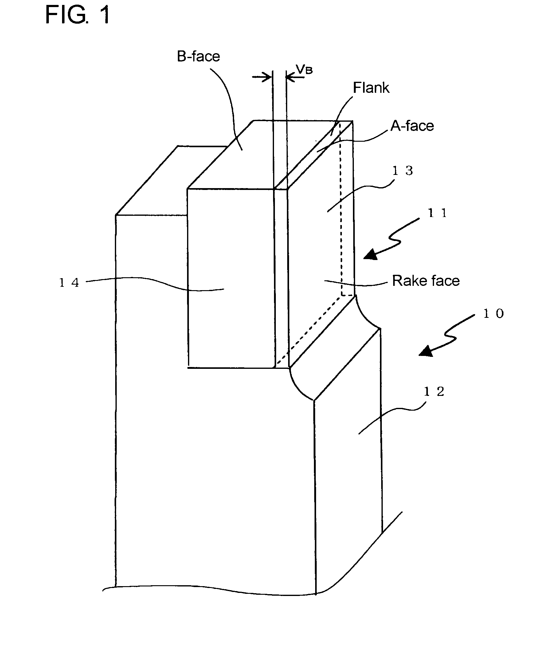
[0055]Hereafter, with reference to FIG. 1, description will be made regarding a first embodiment in which a cutting tip according to the present invention is employed for a bite used in a lathe or the like. The bite 10 is used by being attached to a bite holder of a lathe or the like and is composed of a shank portion 12 (mounting portion) secured to the bite holder and a cutting tip 11 brazed to be secured to the shank portion 12.

[0056]The cutting tip 11 is composed of a cutting edge portion 13 and a support portion 14 and takes a construction that the cutting edge portion 13 is supported by the support portion 14 on the reverse side of a rake face thereof. The cutting tip 11 is so constituted that an extreme end face B-face of the support portion 14 and an extreme end face A-face of the cutting edge portion 13 become even in height, and is secured with a solder taking sliver solder as chief ingredient so that slide or detachment does not occur between the cutting edge portion 13 a...

fourth embodiment

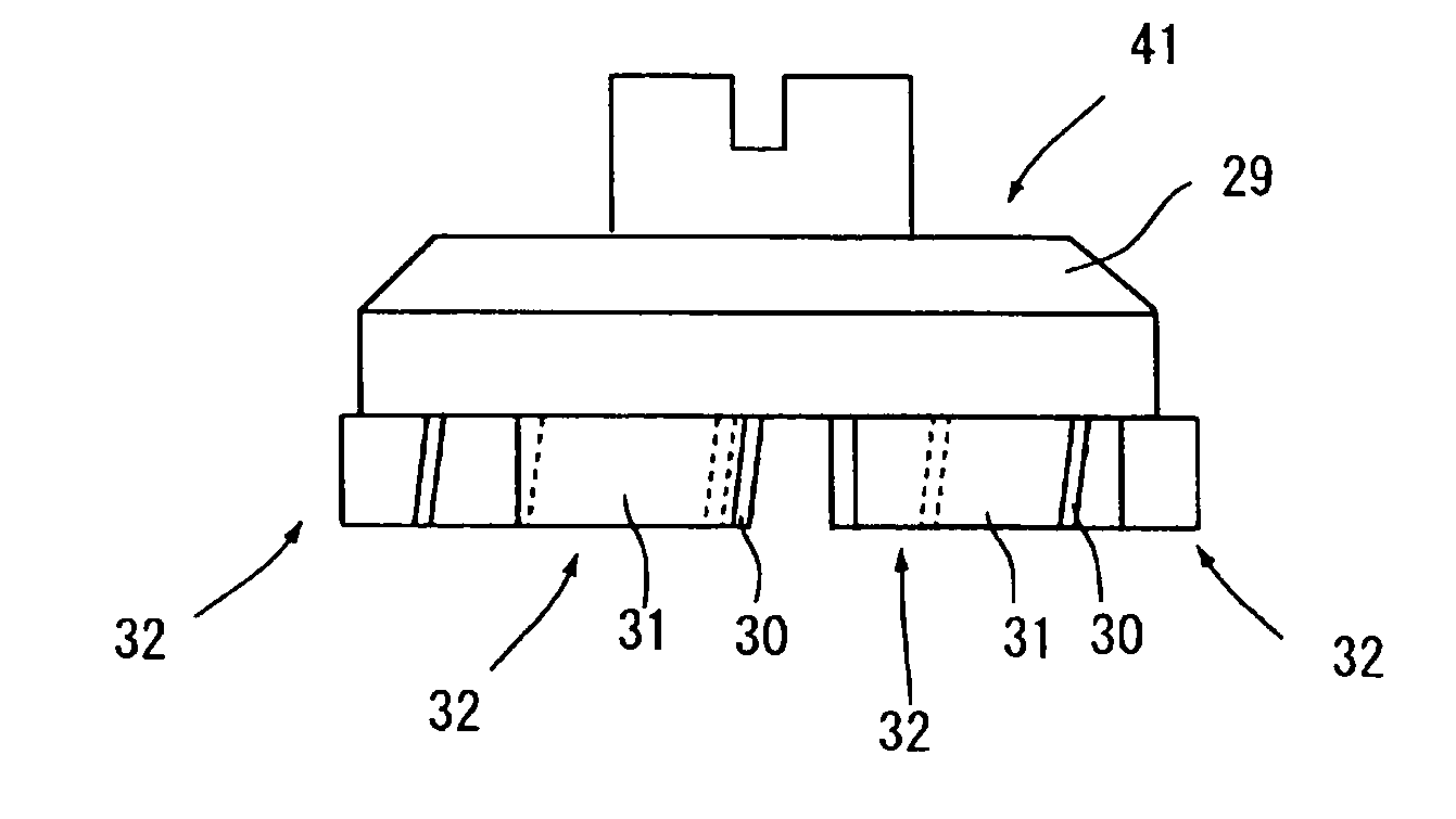
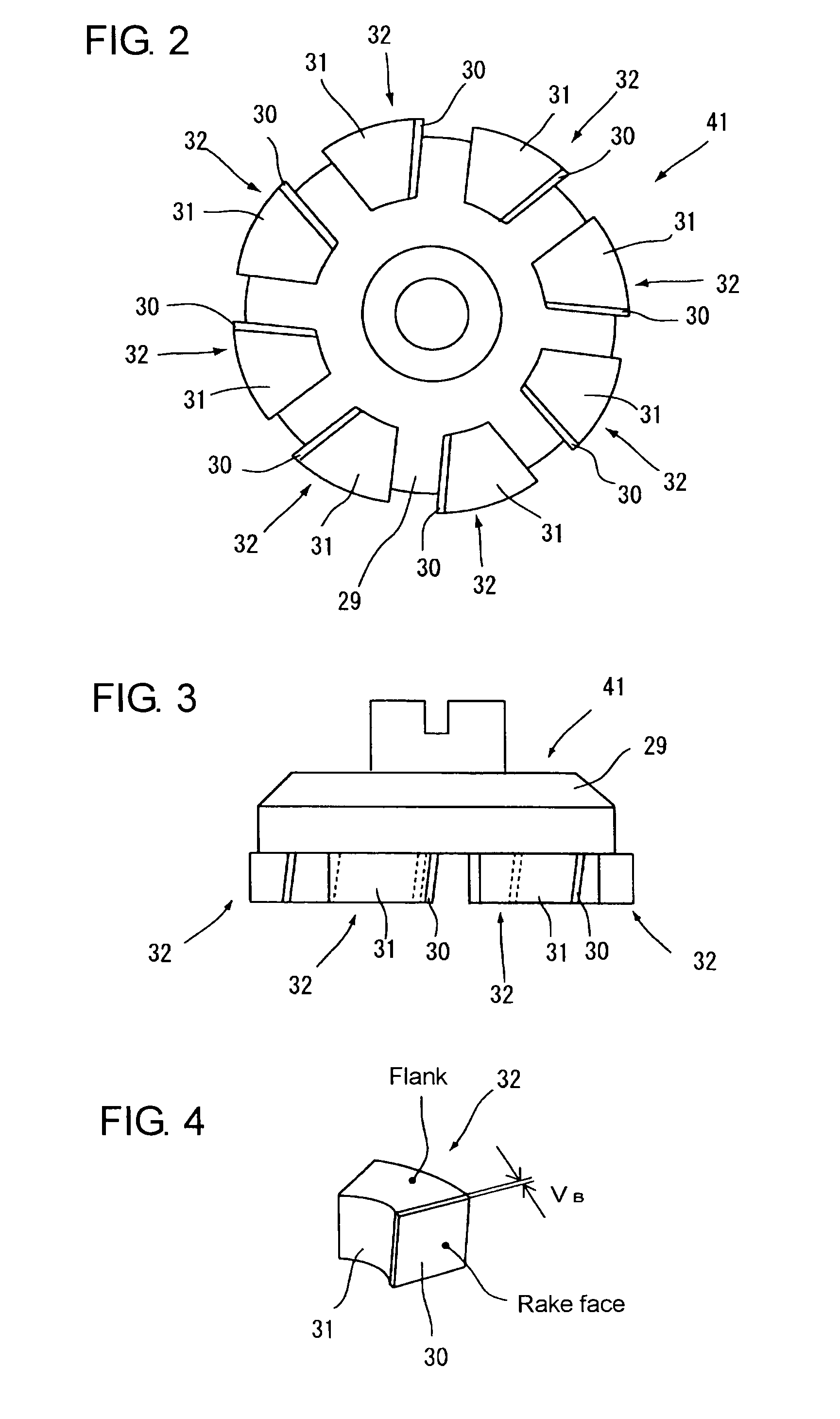
[0081]As shown in FIG. 9, in the fourth embodiment, eight cutting tips 35 are secured by fastening means of screws or the like on an outer circumference of a cutting tool body 38 through cutting tip bodies 87 to constitute a milling tool 34. The cutting tips 35 are so-called formed cutting tips which have the shape of their edges formed to be the same as the groove shape (the shape to be machined) on the workpiece W.

[0082]With rotation of the milling tool 34, the eight cutting tips 35 secured to the outer circumference of the cutting tool body 38 through the cutting tip bodies 87 machine the workpiece W intermittently, whereby the edge shape of the cutting tips 35 is transferred as it is to the workpiece W.

[0083]Therefore, because the edge shape of the cutting tips 35 approximates a finish machining shape required to the workpiece W, it is unnecessary to perform the machining many times, so that the machining time can be reduced greatly. Further, the edge shape of the cutting edge p...

sixth embodiment

[0095]In the sixth embodiment, the bite 15 is composed of the shank portion 19 (mounting portion) attached to the bite holder and the cutting tip 18 secured by brazing to the shank portion 19. Without being limited to this, it is possible to make the support portion constituting the cutting tip 18 act the function of a shank and to secure the support portion on the bite holder.

[0096]Further, in the sixth embodiment, since a lapping finish is implemented on the cutting edge portion 20 to remove a heat-affected layer therefrom, the occurrence of chipping can be prevented more reliably, so that the life of the cutting tip 18 can be extended further. Further, since a hard coat such as TiAlN is coated on the flank and the rake face of the cutting edge portion 20 by the utilization of CVD (chemical vapor deposition) or PVD (physical vapor deposition), the effect of preventing the wear of the cutting edge portion 20 is achieved, so that the life can be extended further.

[0097]Further, in th...


PUM

PropertyMeasurementUnit
thicknessaaaaaaaaaa
thicknessaaaaaaaaaa
thicknessaaaaaaaaaa

Abstract

A cutting tip including a cutting edge portion made of a high-hardness material to take a thin-plate shape; and a support portion made of a material which is more worn in contact with a workpiece than the cutting edge portion not to exert a machining action on the workpiece even in contact with the workpiece, and securing and supporting the cutting edge portion on a reverse side of a rake face of the cutting edge portion. Thus, the width of flank wear is prevented from increasing and chipping of the cutting edge is prevented, so that the life of the cutting tip can be extended.

Description

TECHNOLOGICAL FIELD[0001]The present invention relates to a cutting tip used in cutting machines such as lathe, milling machine or the like and a forming method and a manufacturing method of the cutting tip.BACKGROUND ART[0002]Generally, in cutting tips used in cutting machines, many of those use a cemented carbide increased in toughness and hardness as the material for the cutting tips, and with the details in operation taken into consideration, it is unavoidable that the cutting edges are worn away with lapse of machining time. Further, there arises a problem that after being worn away, the cutting tips get the edge shapes changed to increase cutting resistance due to an increase of a contact area with a workpiece and that defects such as chipping occur in due course thereby to reach the end of the service life in a relatively short period of time. In order to solve such a problem, materials for cutting tips have heretofore been improved, as described in JP 11-61316 A.Problem to b...

Claims


Application Information

Patent Timeline
Patent Type & Authority Applications(United States)
IPC IPC(8): B23P15/28B21K21/00
CPCB23B27/145Y10T407/27B23B2224/04B23B2224/24B23B2226/18B23B2226/72B23B2228/04B23B2228/08B23B2228/10B23B2240/08B23C5/18C22C29/08B23B27/14Y10T407/26B23B27/18
Inventor ONO, NAOTOSOMA, SHINJINIINO, YASUOYAMASHITA, TOMOKAZU
Owner JTEKT CORP
Learn More