
Filter Element With Magnetic Array

a filter element and magnetic array technology, applied in magnetic separation, electrical supply techniques, chemistry apparatus and processes, etc., can solve the problems of reducing the life of the fluid system, contaminating the fluid used in the manufacturing process, and ferrous metal particles, etc., and achieves convenient service and effective trapping characteristics.

Inactive Publication Date: 2018-05-24
FLEENOR MFG INC
View PDF5 Cites 2 Cited by
  • Summary
  • Abstract
  • Description
  • Claims
  • Application Information

AI Technical Summary

Benefits of technology

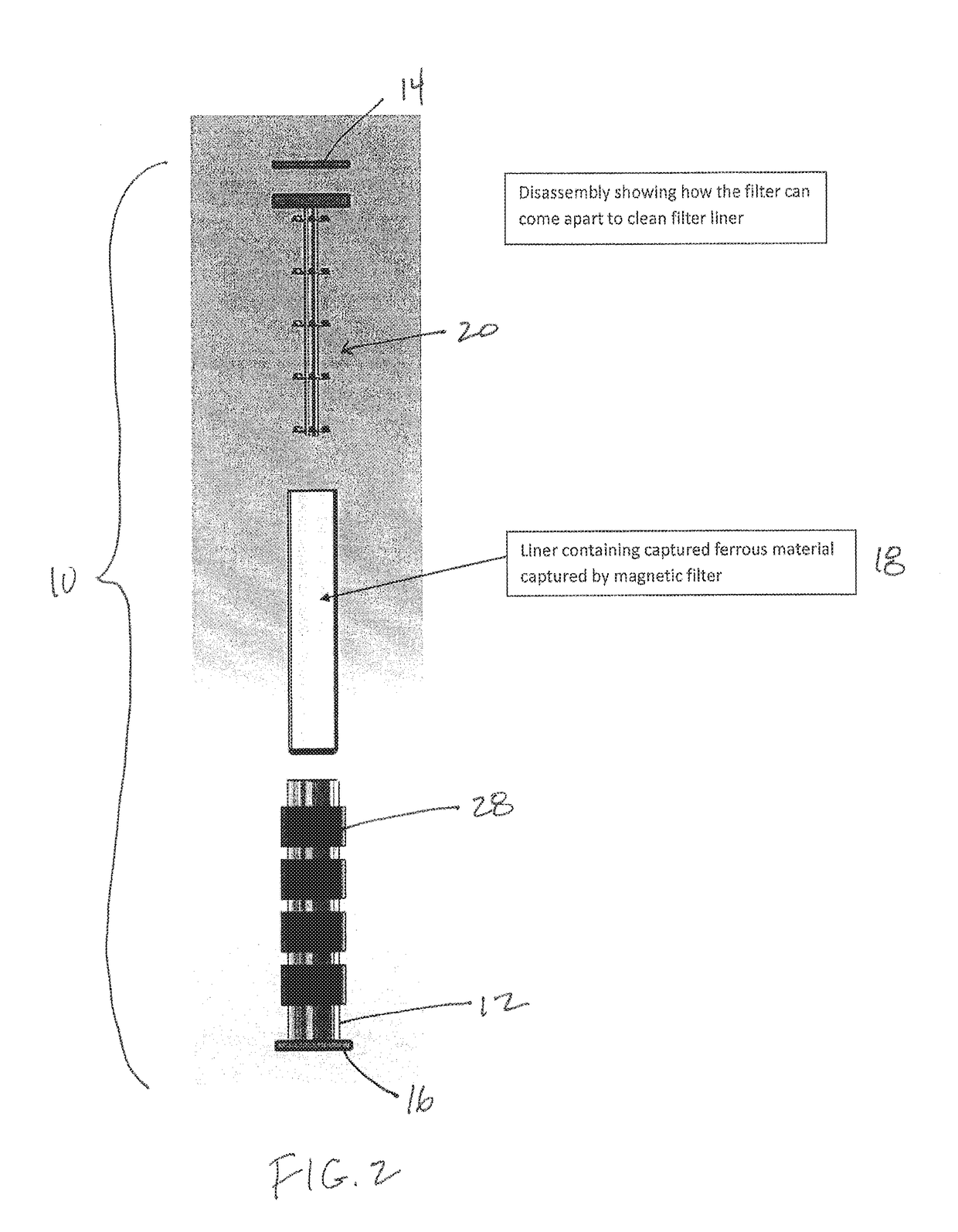
The present invention is a filter element that uses magnetic technology to trap abrasive contaminants, such as ferrous particles, from a fluid system with low service costs. The filter element has a coaxial inner liner with multiple axial magnets placed inside a cylindrical can, which are more effective at trapping ferrous contaminants. The liner is easily removable for replacement or disposal. The filter can be used in parallel circuits or combined with standard filters for absolute filtration. This invention provides a magnetic filters with improved trapping characteristics and easier servicing.

Problems solved by technology

In the process of making hydraulic components, such as gears, pumps, motors, valves and cylinders, ferrous metal particles are produced that contaminate the fluids used in the manufacturing process.
These ferrous particles can result in decreased life of the fluid system.
Filters capable of removing particulate contaminants down to 4 microns are expensive and often must
In operational systems, such as engines, transmissions, and mobile construction equipment hydraulic systems, iron based contaminates will be generated in the normal wear and tear of operation.
Typically, these metal contamination particles are relatively hard and can induce wear in a system.
Many times these systems are operated outside in cold environments and putting in a fine filter medium to trap effectively these fine particles can have a negative impact on performance due to the increased pressures from the high viscosity of low temperature oil.
Therefore, the filters used tend to be higher in absolute micron rating which allows larger contaminants to flow through the system and ultimately leads to lower component life.

Method used


Image

  • Filter Element With Magnetic Array
  • Filter Element With Magnetic Array
  • Filter Element With Magnetic Array

Examples


Embodiment Construction

[0020]Illustrated in FIGS. 1 and 2, generally at 10, is a preferred embodiment of a filter element of the present invention. The filter element 10 includes a cylindrical filter housing 12 to which is affixed a top plate 14 and a bottom plate 16. A non-ferrous liner 18 is received in a close fit inside the housing 12. An insert 20 extends from the top plate 14 axially down the housing 12, terminating above the bottom plate 16. The insert 20 includes a central return tube 22. Fluid is directed into the filter element 10 through a port 24 in the top plate 14 and is returned to the exterior of the filter element 10 via the return tube 22. The insert 20 preferably has a plurality of radially extended plates 26 that act to introduce a flow pattern to fluid inside the filter element 10. Encircling the exterior of the filter housing 12 are a plurality of annular rings of magnets 28 which will act to attract ferrous contaminants present in the fluid where they will be held against the liner ...


PUM


Abstract

A filter for removing ferrous particles from a fluid. The filter has an outer filter housing and a non-ferrous liner inside the housing. A plurality of magnets are longitudinally extended at intervals outside the liner. An insert inside the liner imparting a directional flow to the fluid inside the filter whereby ferrous particles in the fluid are trapped by the magnets and held against the non-ferrous line.

Description

CROSS-REFERENCE TO RELATED APPLICATION(S)[0001]This application claims priority to International PCT Application No. PCT / US16 / 30119 filed on Apr. 29, 2016 which claims priority to U.S. Provisional Application No. 62 / 154,465 filed Apr. 29, 2015 and entitled “Filter Element with Magnetic Array,” which is hereby incorporated by reference in its entirety under 35 U.S.C. § 119(e).BACKGROUND OF THE INVENTION[0002]The invention relates generally to filter elements and, more specifically, to a novel, non-obvious filter element having a magnetic array for assisting in the removal of ferrous particles from a fluid flow.[0003]In the process of making hydraulic components, such as gears, pumps, motors, valves and cylinders, ferrous metal particles are produced that contaminate the fluids used in the manufacturing process. These ferrous particles can result in decreased life of the fluid system. Current ISO standards require the removal of particles down to the level of 4 microns. Filters capabl...

Claims


Application Information

Patent Timeline
IPC IPC(8): B03C3/66B03C1/033B03C1/034B03C3/47B03C1/28B03C3/82
CPCB03C3/66B03C1/0332B03C1/034B03C3/47B03C1/288B03C3/82B03C2201/18B03C2201/28B03C1/284B03C1/30B03C1/286B03C2201/22
Inventor FLEENOR, JEFFSTOCKDALE, KURTIS
Owner FLEENOR MFG INC
Learn More