
Dual mode transceiver

a transceiver and dual-mode technology, applied in the field of communication methods and systems, can solve the problems of wasting rf energy that otherwise would have been provided, reducing the overall effect of switching signals, and facilitating the implementation of switches with limited loss,

Active Publication Date: 2010-08-12
SIGE SEMICON
View PDF6 Cites 57 Cited by
  • Summary
  • Abstract
  • Description
  • Claims
  • Application Information

AI Technical Summary

Benefits of technology

"The invention provides a circuit and method for switching between different signal paths using a switching circuit. The circuit has filters for receiving and transmitting signals, and the method allows for switching between the filters to switch between different signal paths. This allows for more flexibility and versatility in signal processing."

Problems solved by technology

Advantageously, switches are easily implemented with limited loss and limited overall effect on switched signals.
The impact of the losses in transmission is, effectively, wasted RF energy that otherwise would have been provided to the antenna.
On the reception side, filter losses mean that less signal energy is available for processing by the receiver and as a consequence the range of operation of the device in respect of distance is more limited.
While a same power amplifier (PA) could be used for either a TDD or FDD system, implementing a single system supporting both FDD and TDD and using a same PA is problematic.
The extra duplexer losses incurred in implementing an FDD system—losses from the sharp filter, for example—unduly penalize a TDD system.
Conversely, the switch used to toggle between Tx and Rx modes in a TDD system does not allow for FDD operation, since it will not provide the necessary duplex filtering.
Unfortunately, as noted above, each of these configurations suffers losses associated with the filters in the receive path and the transmit path.
Though overall, the configurations function, they provide reduced power efficiency and, in this regard, are often not cost effective dual mode solutions because of the operational cost imposed—reduced battery life, increased battery cost, etc.

Method used


Image

  • Dual mode transceiver
  • Dual mode transceiver
  • Dual mode transceiver

Examples


Embodiment Construction

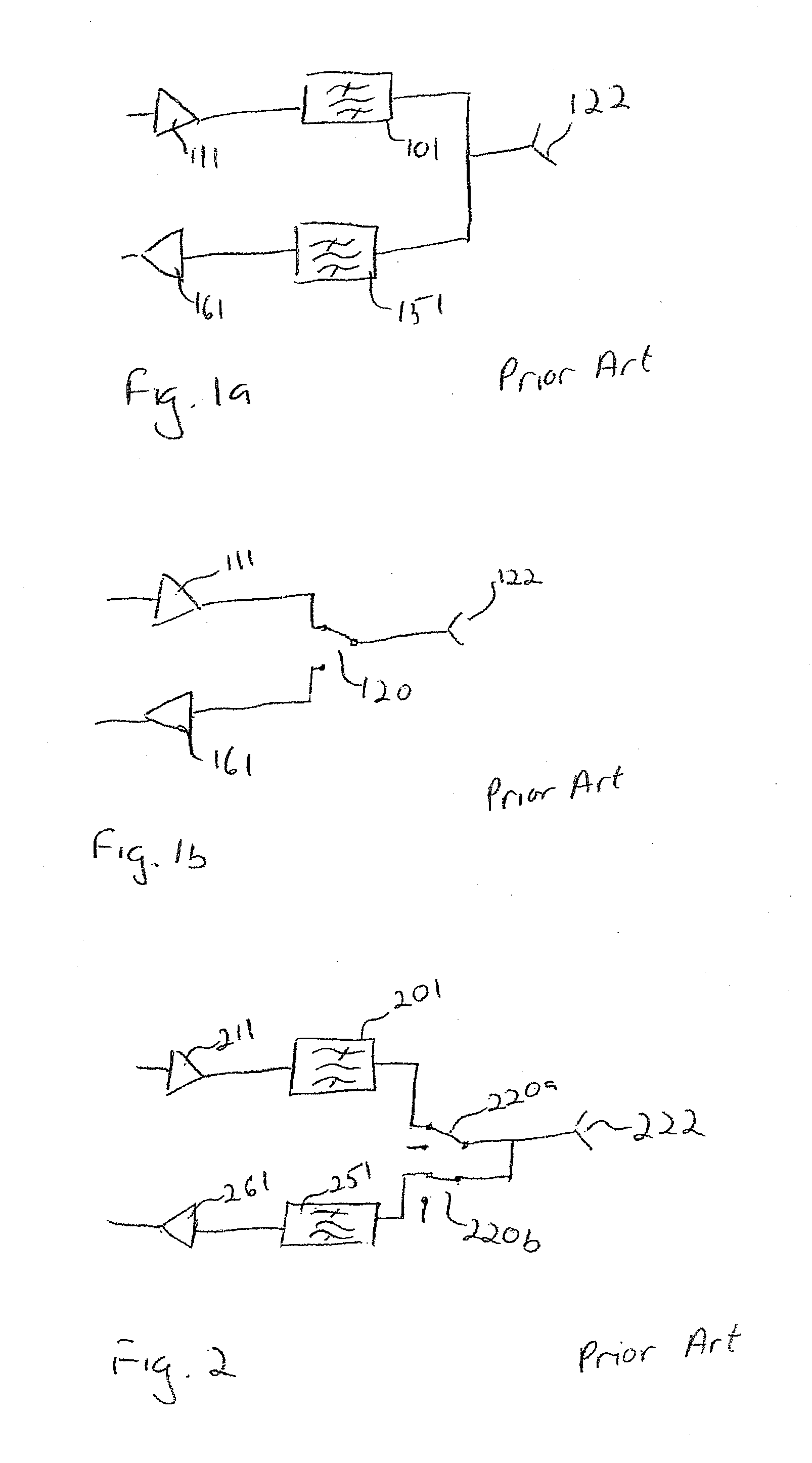
[0021]Referring to FIG. 1a, a prior art FDD circuit is shown. The antenna 122 is coupled to each of two filters 101 and 151. The filter 101 is then coupled to power amplifier 111 forming the transmit portion of the FDD circuit. The filter 151 is coupled to low noise amplifier 161 forming a receive portion of the FDD circuit. The filters 101 and 151 are designed for passing signals within appropriate transmit bands and receive bands, respectively. In this way, the filters act to isolate the transmit band from the receive band which may be closely space in respect of frequency and to isolate the receive band from the closely spaced transmit band.

[0022]Referring to FIG. 1b, a prior art TDD circuit is shown. The antenna 122 is coupled to switch 120. The antenna 122 is switchably coupled to power amplifier 111 forming the transmit portion of the TDD circuit. The antenna 122 is also switchably coupled to low noise amplifier 161 forming a receive portion of the TDD circuit. The switch is a...


PUM


Abstract

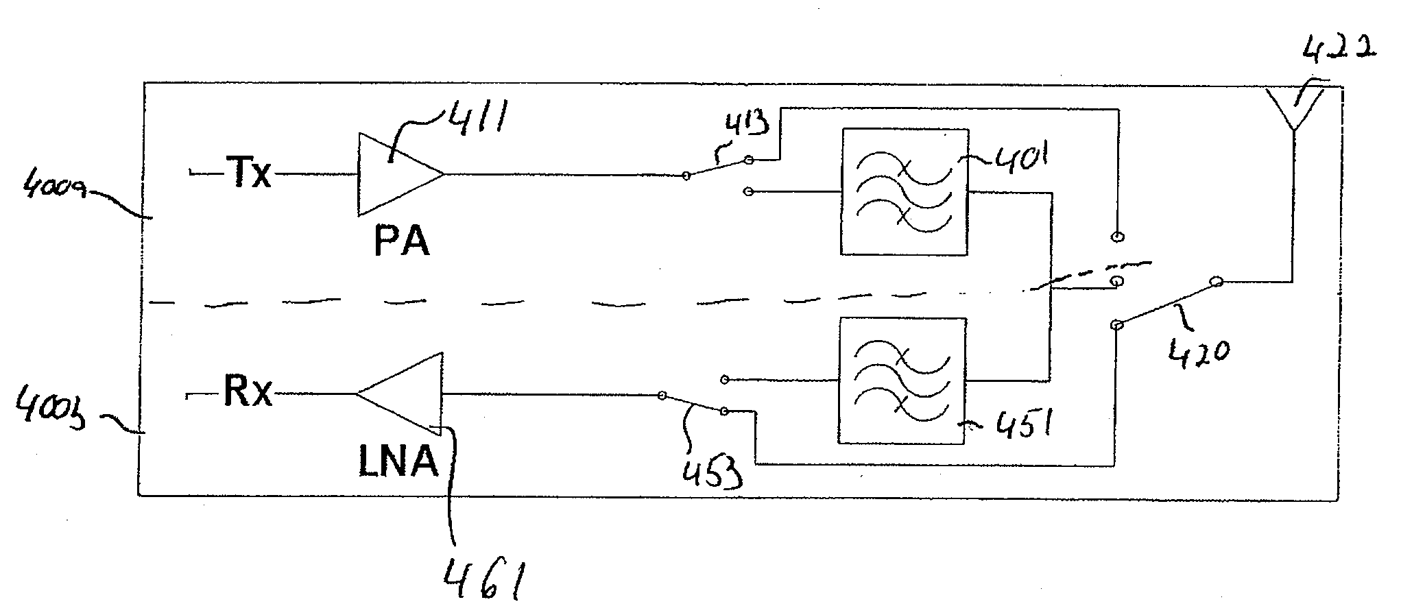
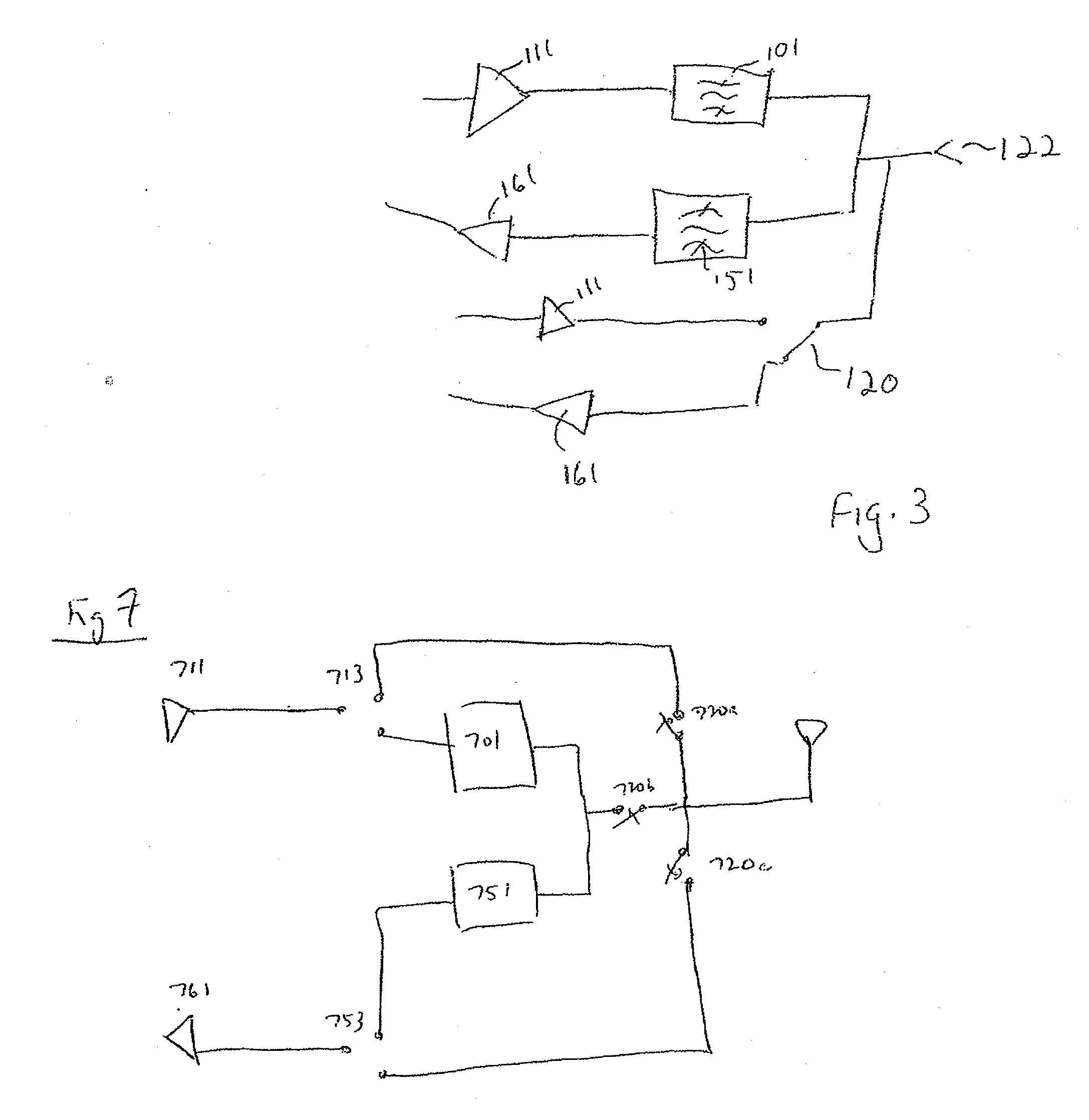
A circuit is disclosed with an external coupling port for coupling to an external antenna, for example. The circuit has an FDD receive path including a narrowband passband filter. The circuit has a TDD receive path bypassing the narrowband passband filter but relying on a same amplifier. The circuit also has an FDD transmit path including a narrowband passband filter. The circuit has a TDD transmit path bypassing the narrowband passband filter of the FDD transmit path but relying on a same transmit amplifier. A switching configuration allows the circuit to operate in TDD mode, alternating between the TDD receive path and the TDD transmit path and in the FDD mode wherein the FDD transmit and receive paths are simultaneously coupled to the external coupling port.

Description

FIELD OF THE INVENTION[0001]The invention relates generally to methods and systems for communication and more particularly to a circuit and method for supporting both time-division-duplex (TDD) and frequency division duplex (FDD) modes of operation in a same transceiver.BACKGROUND[0002]Radio transmission is used widely in various applications. In some applications, a signal is transmitted from a source to a destination for communication in that direction only. One common example is broadcast radio and broadcast television. When broadcast transmission is employed, a broadcaster can transmit a signal continuously for reception without receiving a return signal.[0003]For bi-directional communication, each end of a communication path transmits and receives signals. Two common approaches to supporting bi-directional communication include time-division duplexing (TDD) and frequency-division duplexing (FDD). When a radio operates in TDD mode, it transmits (Tx) and receives (Rx) signals on ...

Claims


Application Information

Patent Timeline
Patent Type & Authority Applications(United States)
IPC IPC(8): H04J4/00H04B1/44H04L5/14
CPCH04L27/0002H04B1/44H04B1/006H04L27/0008H04L5/143H04L5/1469H04B1/525
Inventor POULIN, DARCYGAMMEL, PETER
Owner SIGE SEMICON
Learn More