Stereo display system with scanning of light valves

a display system and light valve technology, applied in the field of display systems, can solve the problems of increasing the cost of the apparatus, unable to instantly switch the part of the right eye image, and the light valve technology based on liquid crystals cannot be instantly switched between displaying the first image, etc., to achieve the effect of reducing the amount of projected light, reducing the amount of leakage, and high quality

Active Publication Date: 2010-08-12
BARCO NV
View PDF8 Cites 13 Cited by
  • Summary
  • Abstract
  • Description
  • Claims
  • Application Information

AI Technical Summary

Benefits of technology

[0016]An advantage of the present invention is that it allows a single projector to display high quality stereoscopic images, with minimal leakage between left and right eye images, while using relatively slowly responding light valve arrays. Since only part of the entire light valve array is illuminated at any time, in view of the shaping of the light beam, the light valve elements can be switched to their new state for the next image during the period when they are not illuminated. This avoids leakage of left eye image into the right eye of a viewer, and vice versa.
[0017]A consequence of illuminating only part of the light valve array at any time is that the amount of projected light is reduced. To compensate for this, it is preferred that a concentrated light source is used. A preferred light source is a laser although another, less desirable, alternative is to use a bulb in combination with optionally suitable apparatus to recover lost light, such as the arrangement described in EP 1 274 256. When a laser is used as the light source, the shaped beam can have a height of the order of several pixels. Alternative suitable light sources include UHP lamps (or other types of lamp) and LEDs. However some light sources have the disa

Problems solved by technology

It is undesirable that any part of a right eye image should be viewed by the left eye, or that any part of a left eye image should be viewed by the right eye.
It is described how this can ensure a good isolation between the left and right eye channels but it has a considerable disadvantage of requiring two projectors, which i

Method used


Image

  • Stereo display system with scanning of light valves
  • Stereo display system with scanning of light valves
  • Stereo display system with scanning of light valves

Examples


Embodiment Construction

[0039]The present invention will be described with respect to particular embodiments and with reference to certain drawings but the invention is not limited thereto but only by the claims. The drawings described are only schematic and are non-limiting. In the drawings, the size of some of the elements may be exaggerated and not drawn on scale for illustrative purposes. Where the term “comprising” is used in the present description and claims, it does not exclude other elements or steps. Furthermore, the terms first, second, third and the like in the description and in the claims, are used for distinguishing between similar elements and not necessarily for describing a sequential or chronological order. It is to be understood that the terms so used are interchangeable under appropriate circumstances and that the embodiments of the invention described herein are capable of operation in other sequences than described or illustrated herein.

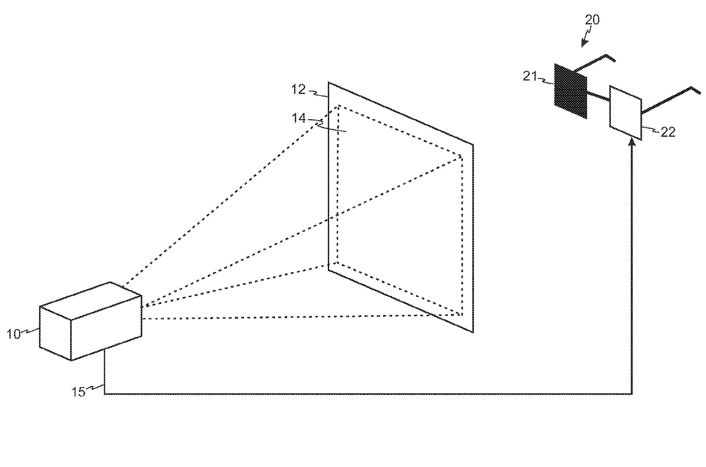
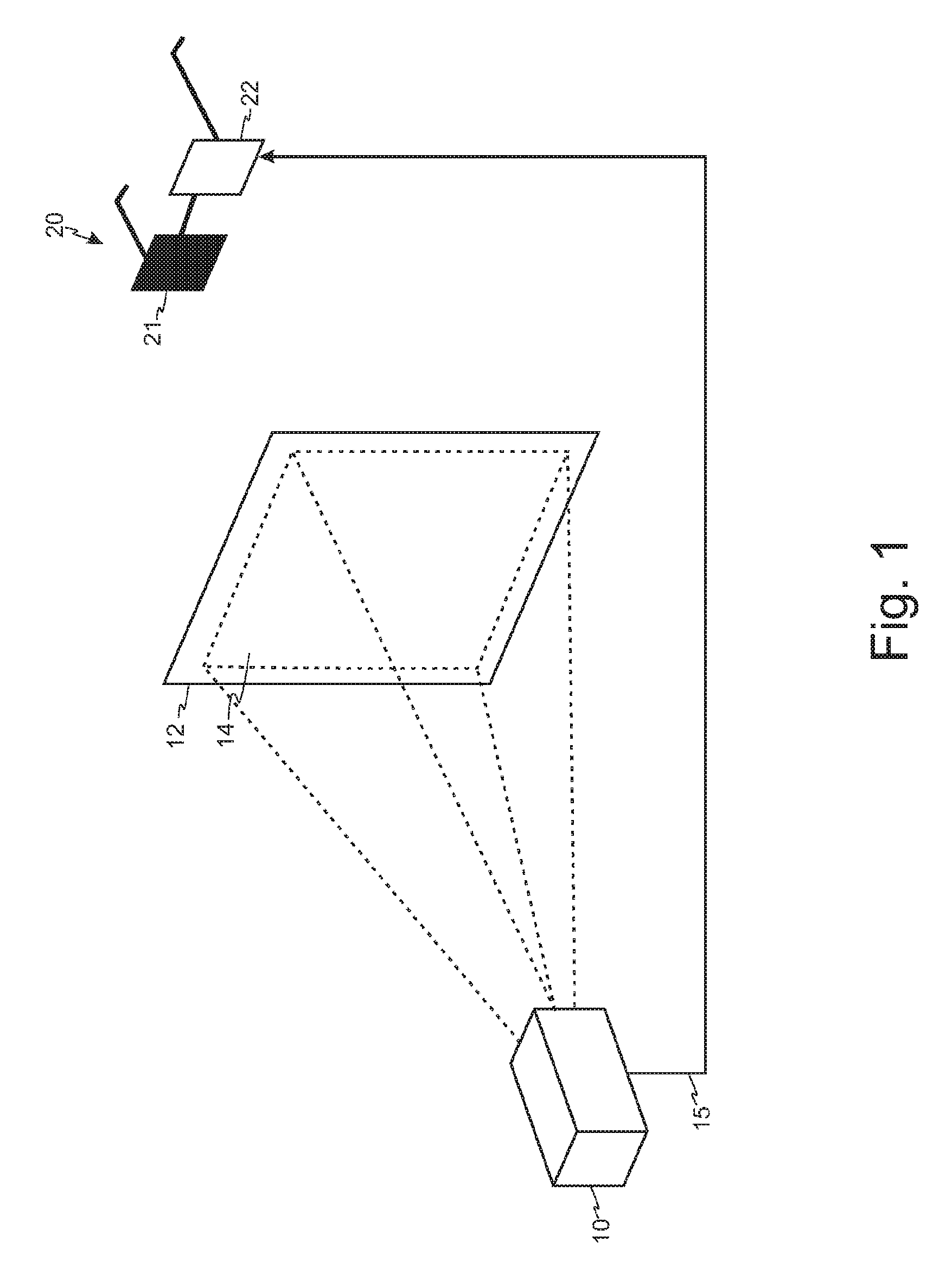
[0040]FIG. 1 shows a display system for project...


PUM


Abstract

A display method and system are described for displaying a stereo image comprising a first image and a second image. A light valve array comprising an array of light valve elements is driven according to an image and a light source is provided for generating a shaped light beam which can illuminate a portion of the light valve array. A scanning device is provided which is arranged to scan the shaped light beam across the light valve array. Light valve elements of the same light valve array are caused to sequentially adopt a state representative of the first image of the stereoscopic image and a state representative of the second image, and to cause the light valve elements to adopt a new state representative of one of the first and second images in advance of the scanning by the shaped light beam and to change to a new state representative of the other of the first and second images during a period between successive scans of the shaped light beam.

Description

FIELD OF THE INVENTION[0001]This invention relates to display systems which form a stereoscopic image by projection, to a method for forming a stereo image, and software for controlling operation of a display system to produce such an image.BACKGROUND TO THE INVENTION[0002]Humans and many animals have binocular vision provided by two eyes which look in the same direction. Two parallel aligned but spaced eyes deliver two slightly different images of the same scene. This is due to the 4 to 6 cm separation between the eyes, which makes each eye have a slightly different viewpoint. The images from these two different viewpoints are sent to the brain, and this difference, which is termed parallax, is interpreted as depth. The nearer an object is to the eyes, the greater the difference between the two images. From the difference between the two images, the brain can display an impression of depth.[0003]It is understood that depth perception, or the capacity to perceive the environment in ...

Claims


Application Information

Patent Timeline
IPC IPC(8): G02B27/22G09G5/10H04N13/398H04N13/363
CPCH04N13/0459H04N13/0438H04N13/341H04N13/363H04N13/398
Inventor MAXIMUS, BARTPRIEM, GINO
Owner BARCO NV
Why Eureka
Try Eureka