
Automated Cleaning Equipment and Method for the Nuclear Fuel-Cladding Tube

a technology of automatic cleaning and fuel-cladding tubes, which is applied in the direction of cleaning using liquids, nuclear elements, and reducing greenhouse gas, etc., can solve the problems of affecting the operation affecting the efficiency of the nuclear reactor, and the technology is not automated, so as to reduce the work time and reduce the productivity and diseases.

Active Publication Date: 2010-08-05
KEPCO NUCLEAR FUEL CO LTD
View PDF5 Cites 5 Cited by
  • Summary
  • Abstract
  • Description
  • Claims
  • Application Information

AI Technical Summary

Benefits of technology

[0014]Therefore, the present invention has been made in order to solve the above problems in the conventional fuel-cladding tube cleaning process, i.e., a decrease in productivity and diseases in the musculoskeletal systems due to manual operation, and it is an object of the present invention to provide an apparatus for and a method of automatically cleaning nuclear fuel-cladding tubes, in which a cleaning material is prepared, automatically injected into and discharged from the fuel-cladding tube, thereby significantly reducing the work time and providing an automation of cleaning.
[0015]Another object of the invention is to provide an apparatus for and a method of automatically cleaning nuclear fuel-cladding tubes, in which the cleaned fuel-cladding tube is automatically inspected, thereby significantly reducing the time required for inspection of tubes and maintaining the degree of cleaning to above a certain level.
[0016]Still another object of the invention is to provide an apparatus for and a method of automatically cleaning nuclear fuel-cladding tubes, in which the nuclear fuel-cladding tubes are automatically transferred during the cleaning process thereof, thereby preventing diseases in the musculoskeletal systems due to manual operation.

Problems solved by technology

However, before nuclear fuel pellets are put into the cladding tube, the cladding tube may contain dust, stain, moisture or the like thereinside.
In this case, these may affect operation of the nuclear reactor.
In addition, even after the cladding tube cleaning is completed, if a cleaning material remains inside the cladding tube, an accident may be caused.
However, the above technology is not directed to cleaning a cladding tube before use.
In addition, this technology is not automated and thus cannot perform a rapid cleaning of a large amount of cladding tubes.
Therefore, in case where a cleaning material is manually pushed into the inside of a cladding tube and an air gun is used to clean the tube, a large quantity of time is required to thereby unable to clean a massive amount of tube and degrade the productivity, and also cause a risk of occurrence of musculoskeletal disease due to the repeated manual work.
Firstly, during the process, a cleaning material charge and discharge consumes a lot of time to thereby extend the process time and degrade the efficiency and productivity.
Secondly, the tube inspection process after cleaning must be performed one by one for every single cladding tube.
Thirdly, the cladding tube must be manually transferred to each working place and the above jobs all must be manually carried out, thereby leading to excessive use of muscles and joints of workers, which may cause diseases in the musculoskeletal systems.

Method used


Image

  • Automated Cleaning Equipment and Method for the Nuclear Fuel-Cladding Tube
  • Automated Cleaning Equipment and Method for the Nuclear Fuel-Cladding Tube
  • Automated Cleaning Equipment and Method for the Nuclear Fuel-Cladding Tube

Examples


Embodiment Construction

[0057]Hereinafter, an embodiment of the present invention will be described in detail with reference to the accompanying drawings.

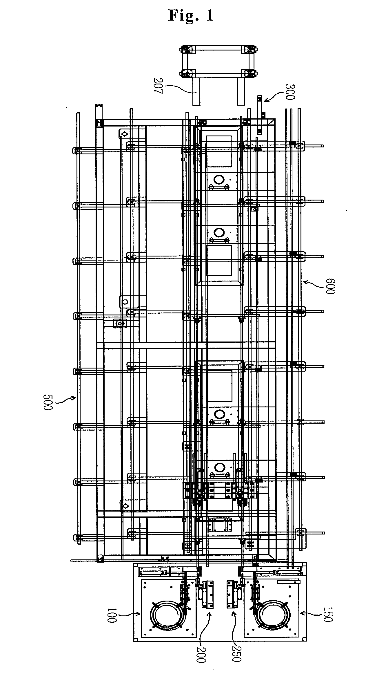
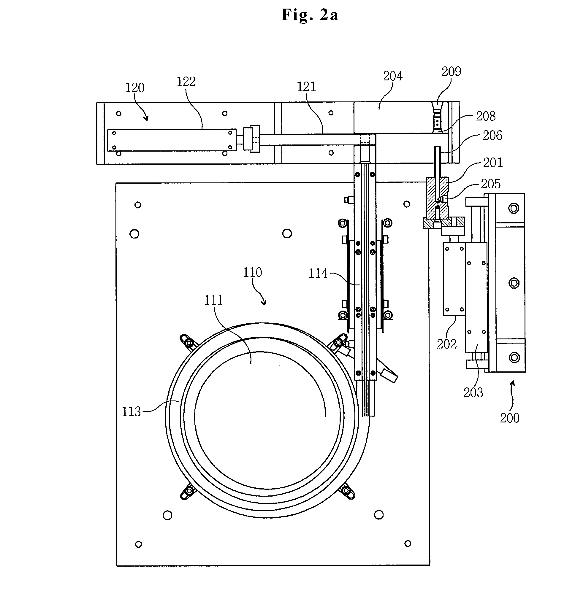
[0058]FIGS. 1-5 show the construction of an apparatus of automatically cleaning nuclear fuel-cladding tubes according to an embodiment of the invention.

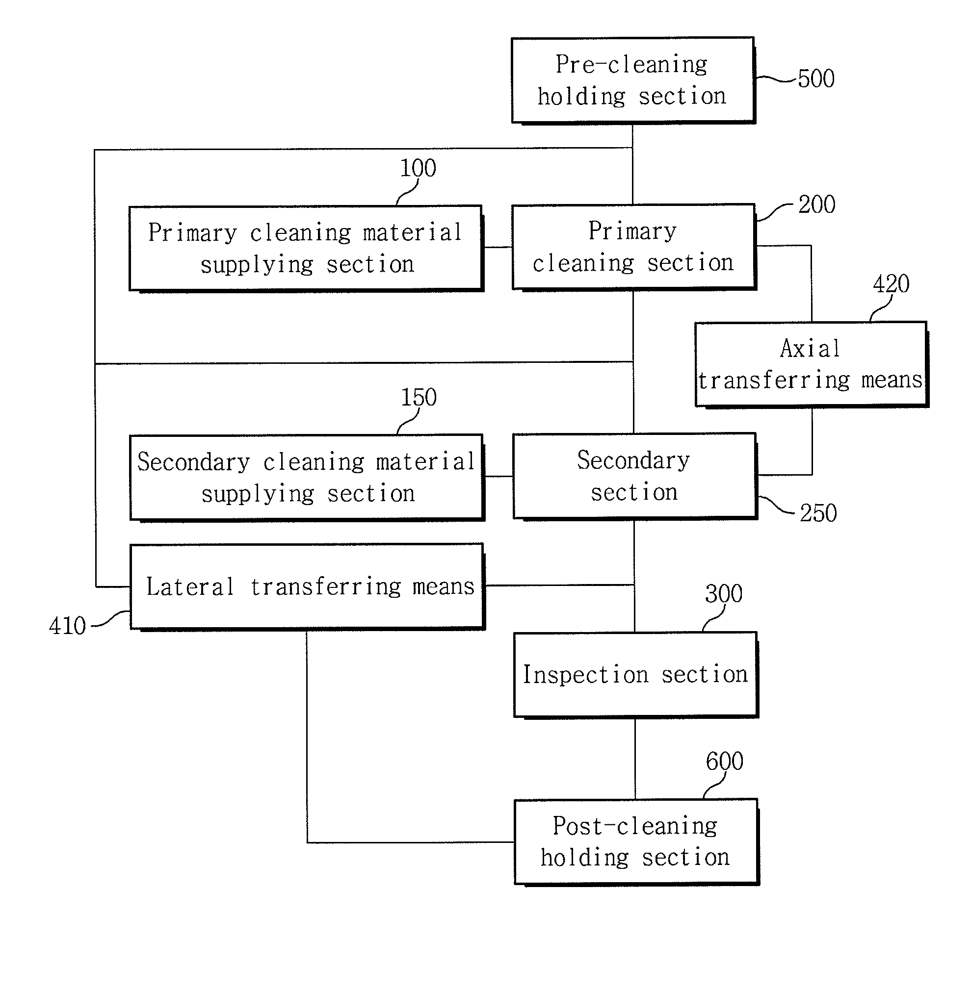
[0059]The automated cleaning apparatus of this embodiment includes a pre-cleaning holding section 500 disposed at one side of a transferring section and made of a cladding-tube guide 414. Before cleaning, the cladding-tubes are loaded in the pre-cleaning holding section 500 and wait cleaning. The apparatus includes a primary cleaning section 200 disposed at the front side of the transferring section and a secondary cleaning section 250 disposed at the front side of the transferring section and also at the lateral side of the primary cleaning section 200, and an inspecting section 300 disposed at the front side of the transferring section and also at the lateral side of the secondary cleaning section. The a...


PUM


Abstract

Disclosed is an apparatus for performing an automated cleaning of nuclear fuel cladding-tubes. The apparatus comprises a pre-cleaning holding section disposed at a first side of the apparatus, a primary cleaning-material supplying section and a primary cleaning section disposed at a second side of the apparatus, a secondary cleaning section and a secondary cleaning material supplying section disposed at the second side of the apparatus and beside the primary cleaning section, an inspection section disposed at a third side of the apparatus that is opposite to the second side, and a post-cleaning holding section disposed at the fourth side of the transferring section. The pre-cleaning holding section and the post-cleaning holding section includes a cladding-tube guide where the cladding-tube is loaded before and after cleaning. Primary and secondary cleaning material supply sections are disposed at a lateral side of the primary and secondary cleaning sections respectively.

Description

CROSS-REFERENCE TO RELATED APPLICATIONS[0001]This a Divisional application of U.S. application Ser. No. 11 / 466,500 filed Aug. 23, 2006, which claims priority from Korean Patent Application No. 10-2006-0054405, filed Jun. 16, 2006, in the Korean Intellectual Property Office, the entire contents of which is incorporated herein by reference.BACKGROUND OF THE INVENTION[0002]1. Field of the invention[0003]The present invention relates to an apparatus for and method of performing an automatic cleaning of nuclear fuel-cladding tubes, more specifically to an apparatus for and a method of automatically cleaning nuclear fuel-cladding tubes, in which a cleaning material is automatically prepared and sprayed to efficiently clean the inside of the nuclear fuel-cladding tube.[0004]2. Background of the Related Art[0005]Nuclear fuel is manufactured under high temperature and pressure conditions using uranium compounds. The nuclear fuel is enclosed by aluminum or magnesium cladding such nuclear wast...

Claims


Application Information

Patent Timeline
Patent Type & Authority Applications(United States)
IPC IPC(8): G21F9/00
CPCB08B9/055B08B9/0551B08B9/0553G21C21/02G21Y2004/503G21Y2002/205G21Y2002/304G21Y2004/30G21Y2004/401G21Y2002/201Y02E30/30B05B7/04B08B3/02B08B5/02B08B9/027B08B9/46G01N21/94
Inventor KWON, KI-JUNKIM, JEONG-HOSHIN, SE-YONGCHANG, HUNG-SOONNA, TAE-HYUNGHONG, JONG-SUNG
Owner KEPCO NUCLEAR FUEL CO LTD
Learn More