
Quantum cascade detector type device with high injector

a detector type, detector type technology, applied in semiconductor devices, lasers, semiconductor lasers, etc., can solve the problems of laser type and laser threshold degradation, and achieve the effect of limiting doping

Inactive Publication Date: 2010-08-05
THALES SA
View PDF7 Cites 11 Cited by
  • Summary
  • Abstract
  • Description
  • Claims
  • Application Information

AI Technical Summary

Benefits of technology

[0012]This is why the subject of the present invention is a novel type of detector-type quantum cascade device compri

Problems solved by technology

This type of laser is, however, limited by the fact that the carriers introduced by the doping of the structure for the electronic transport introduce optical losses and therefore degrade the laser threshold.

Method used


Image

  • Quantum cascade detector type device with high injector
  • Quantum cascade detector type device with high injector
  • Quantum cascade detector type device with high injector

Examples


Embodiment Construction

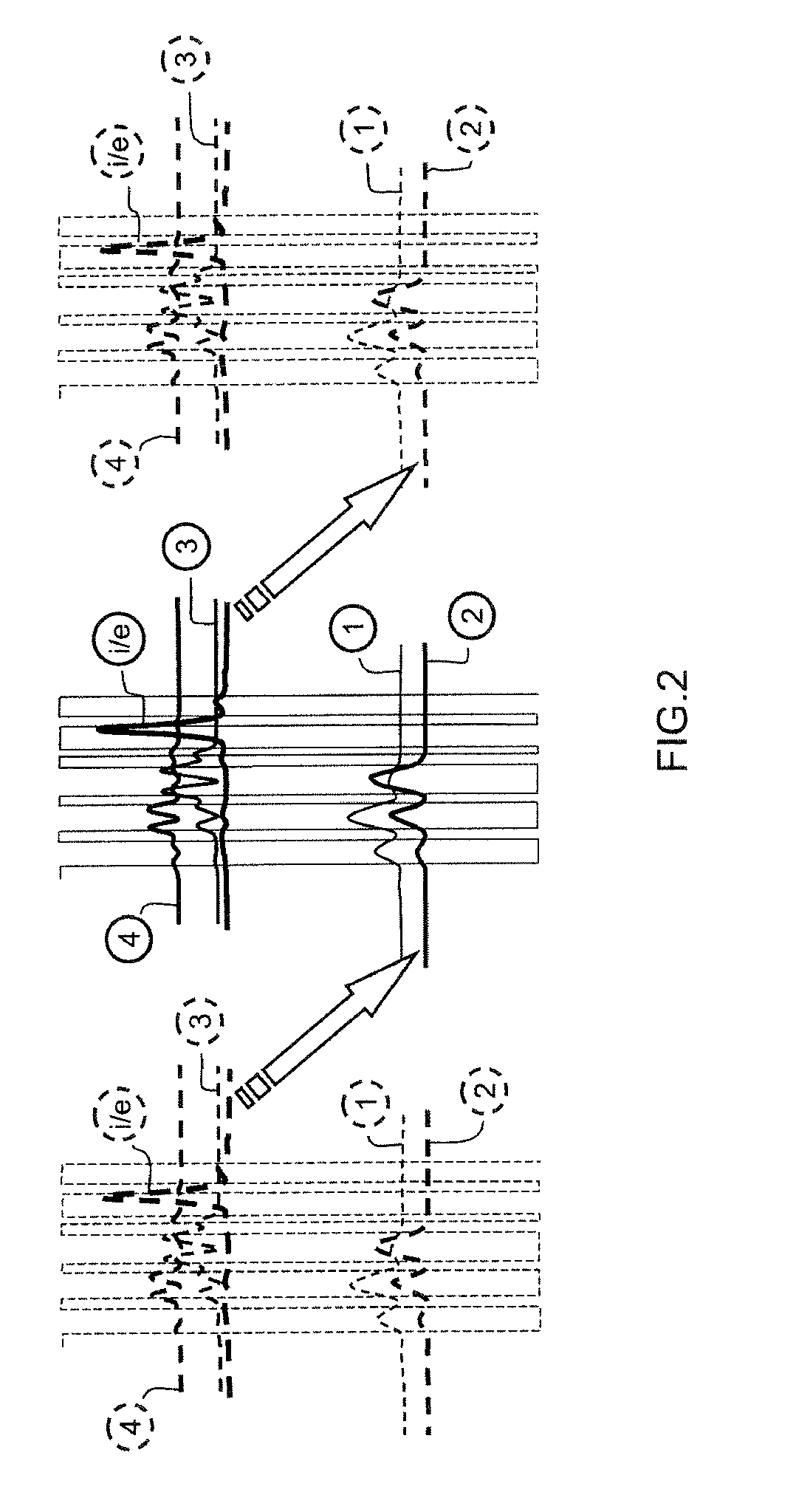
[0025]Advantageously, the inventive device behaves like a detector device in the absence of any applied electrical field.

[0026]To this end, FIG. 2 illustrates the position of the different subbands i, 4, 3, 2 and 1. In the absence of any applied field, the subband 2 is positioned at a level below that of the subband 1.

[0027]Generally, when photons of energy E=hv are absorbed by the quantum cascade device, charge carriers are made to pass from the subband 2 to the subband 3, the collection by an external electrical circuit of these electrons being able to be implemented at the level of the third subband to which they have been carried by infrared lighting, so enabling the detection of this lighting. According to the principle that is then used, the electrodes situated on a bottom level subband are carried to an upper level subband, enabling them to be extracted.

[0028]According to the inventive device, the subband corresponding to the injector level i becomes the extractor level. In p...


PUM


Abstract

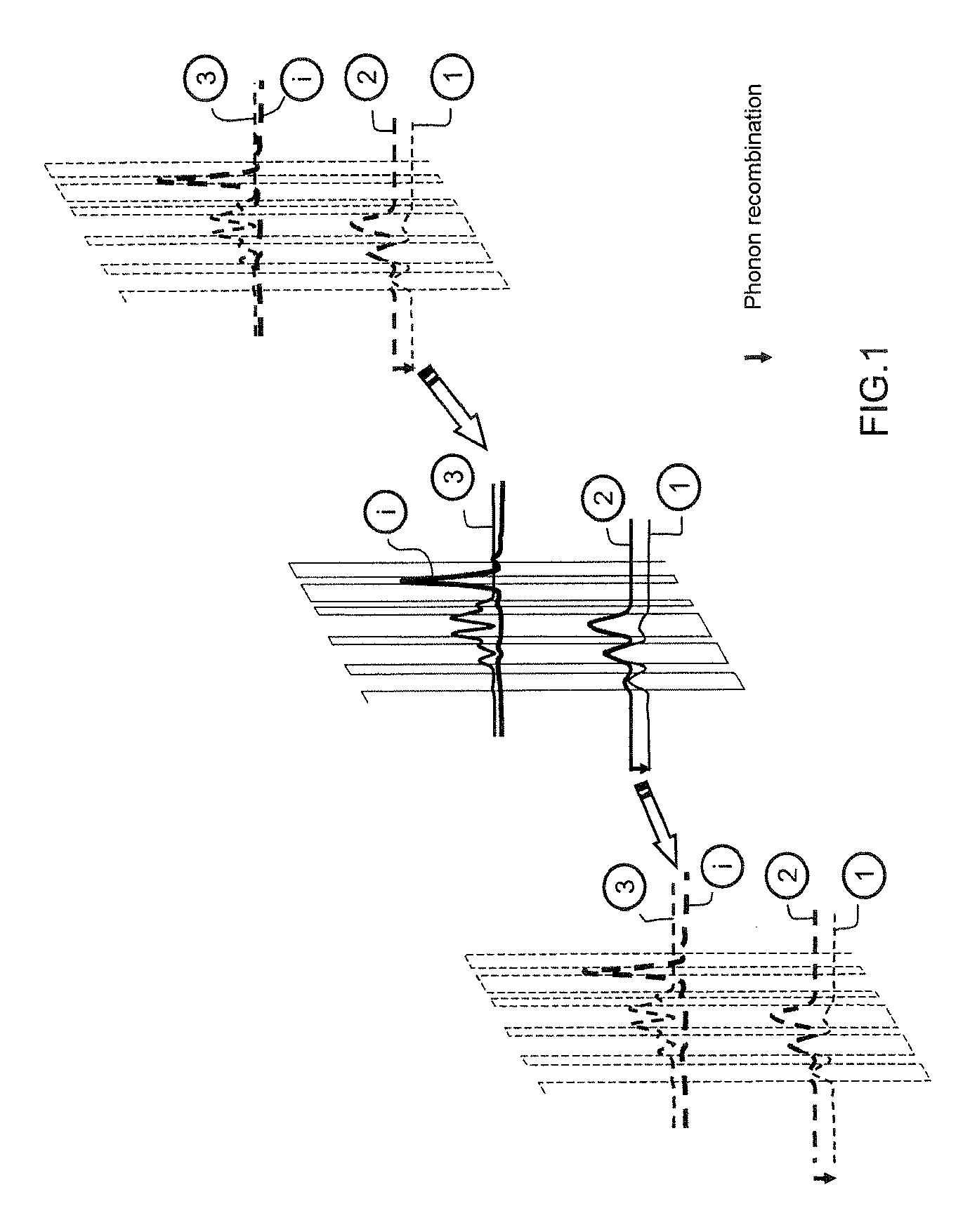
The invention relates to a quantum cascade device of detector type comprising two electrodes for applying a control electrical field, and a waveguide positioned between the two electrodes, said device comprising a gain region made up of a plurality of layers and comprising alternating strata of a first type each defining a quantum barrier and strata of a second type each defining a quantum well, each layer of the gain region comprising an injection barrier exhibiting an injection subband of charge carriers with a lower energy level called injector level (i) and an active area, said active area being made of a set of pairs of strata made from semiconductive materials so that each of the wells has at least one upper subband called third subband (3), a middle subband called second subband (2) and a bottom subband called first subband (1), the potential difference between the third and second subbands being such that the transition of an electron from the third subband to the second subband emits an energy corresponding to that needed for the emission of a photon, characterized in that:the active area also has a fourth subband (4) situated above the third subband;said fourth subband being such that, in the absence of any electrical field applied to the electrodes, the injector level of the injection barrier is less than the level of said fourth subband and greater than the level of the third subband and that, in the presence of a field applied to the electrodes, the charge carrier injector level (i) becomes greater than or equal to the level of the fourth subband, so as to generate a rapid relaxation phenomenon between the injector level and the fourth subband, the fourth subband being at a distance energy-wise from the third subband allowing an optical phonon relaxation.

Description

PRIORITY CLAIM[0001]This application claims priority to French Patent Application Number 08 03812, entitled Dispositif de type détecteur à cascades quantiques à injecteur haut, filed on Jul. 4, 2008.[0002]The field of the invention is that of quantum cascade devices in the mid-infrared and typically in the 3-10 micron wavelengths, generated from semiconductor materials III-V.BACKGROUND OF THE INVENTION[0003]Generally, quantum cascade lasers are known that comprise two electrodes for applying a control electrical field, a waveguide positioned between the electrodes and a structure comprising a gain region made up of a plurality of layers that comprise alternating strata of a first type each defining a quantum barrier and strata of a second type each defining a quantum well, these strata being made of first and second semiconductor materials, respectively constituting barriers and wells.[0004]The structure also comprises two optical containment layers arranged either side of the gain ...

Claims


Application Information

Patent Timeline
IPC IPC(8): H01S5/34
CPCB82Y20/00H01S5/3402H01L31/09H01L31/035236
Inventor CARRAS, MATHIEU
Owner THALES SA
Learn More