
Male push lock pipe connection system

a push lock and pipe connection technology, applied in the direction of hose connections, pipe joints, couplings, etc., can solve the problems of glued or cemented connections that cannot be disconnected, threaded connections that cannot withstand high tensile forces, and pipes that cannot be connected

Active Publication Date: 2010-08-05
AQSEPTENCE GROUP INC
View PDF87 Cites 33 Cited by
  • Summary
  • Abstract
  • Description
  • Claims
  • Application Information

AI Technical Summary

Benefits of technology

[0008]The pipe of the present invention provides the advantage of a connection that can be quickly formed between pipes of the same or different materials. In addition, the connection formed between two similar, adjacent pipes may have a comparatively high tensile yield strength.
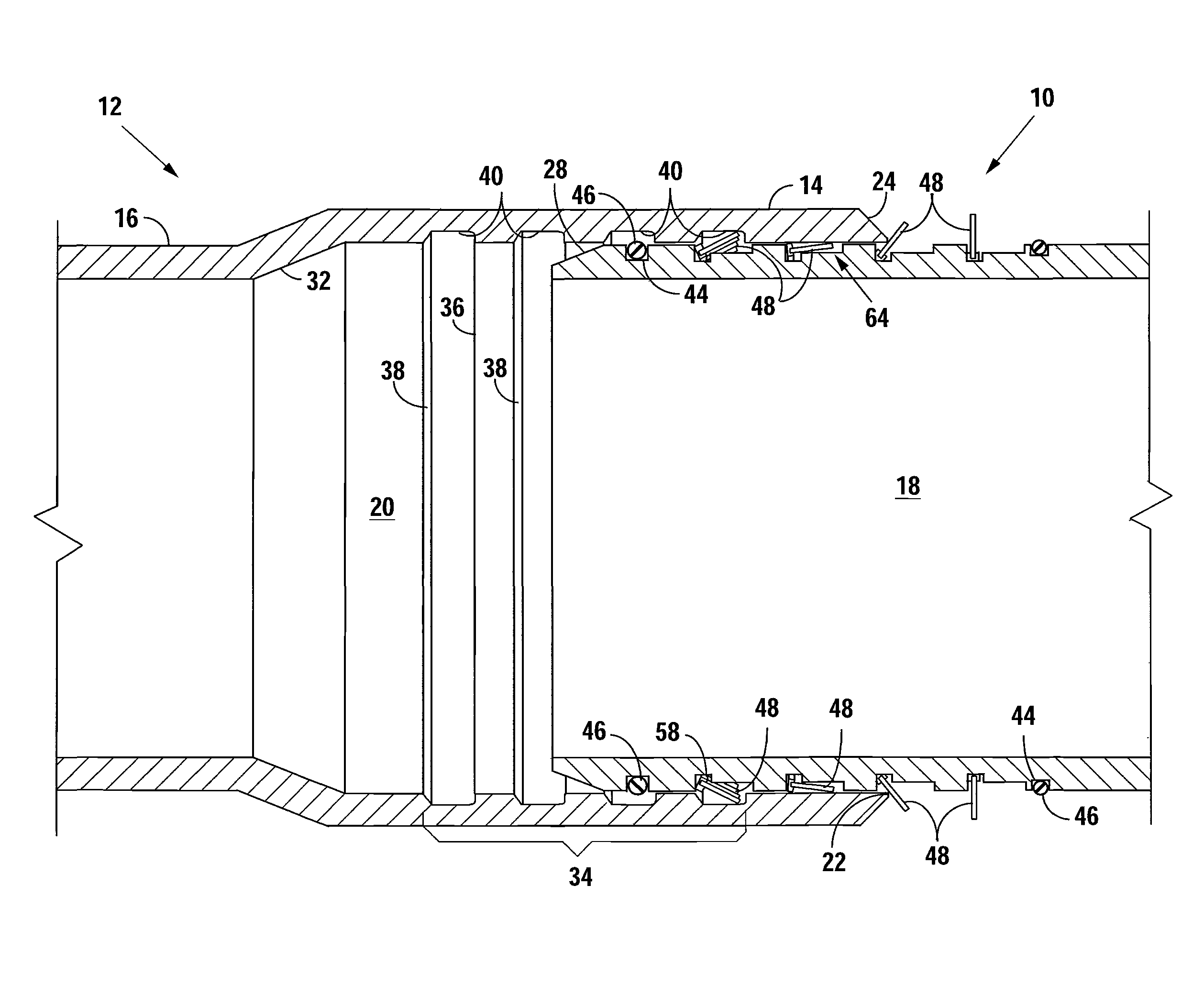
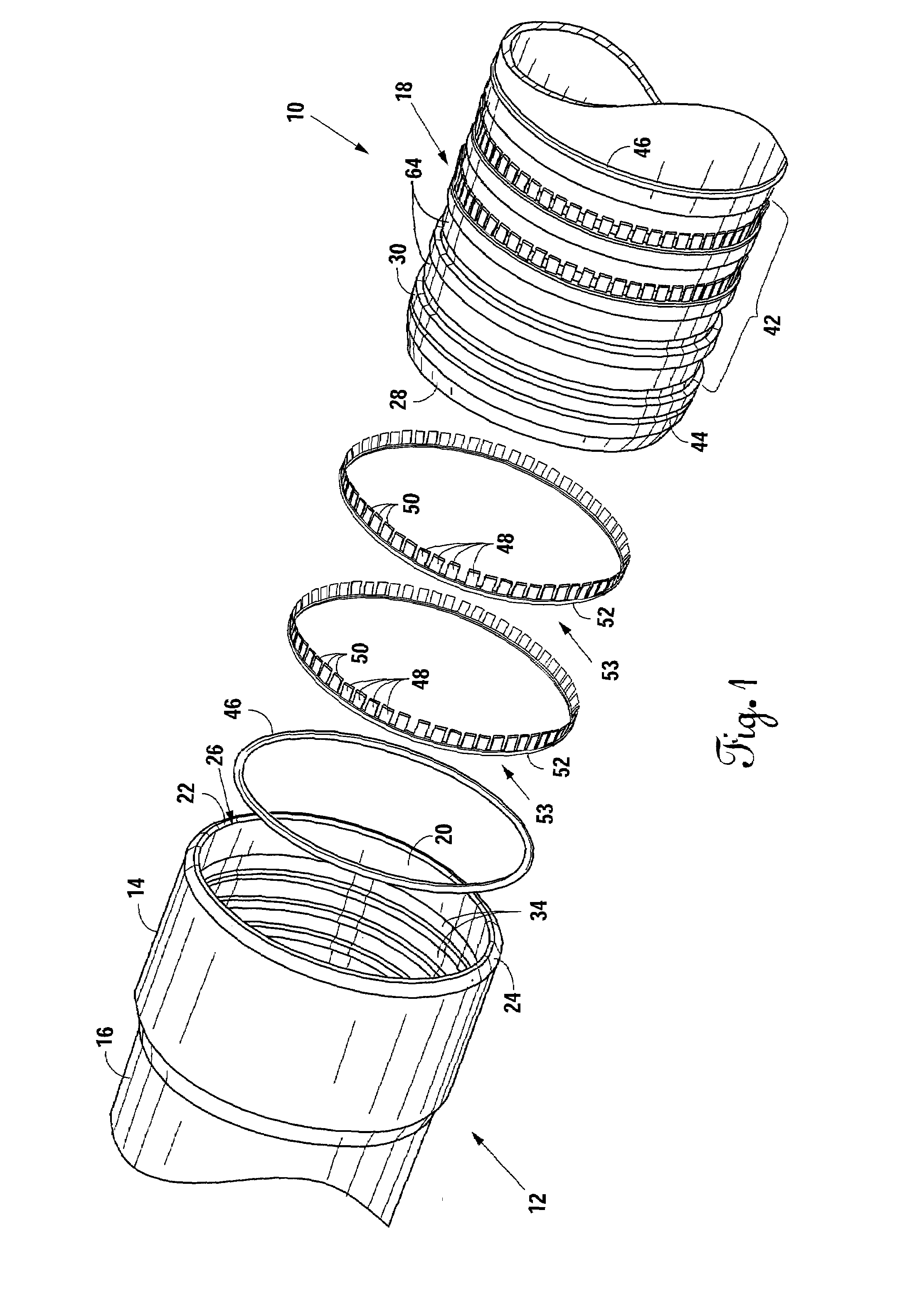
[0009]The pipe of the present invention has a female end for receiving a male end of a similar adjacent pipe. The interior surface of the female end has interior circumferential grooves and the exterior surface of the male end has corresponding exterior circumferential grooves. When the male end of the similar adjacent pipe is fully inserted into the female end, rigid fingers extending from the exterior circumferential grooves of the male end are received within the interior circumferential grooves of the female end and prevent the male end from being withdrawn.
[0013]The interior circumferential grooves on the female end are configured to receive the rigid fingers extending from within the exterior circumferential grooves on the male end of a similar adjacent pipe. During insertion of the male end into the male end receiving chamber, the rigid fingers on the male end are displaced in a direction toward the exterior surface of the male end so the male end can be fully inserted into the female end. When the male end is fully inserted into the male end receiving chamber the rigid fingers extending from the exterior circumferential grooves on the male end are positioned within corresponding interior circumferential grooves on the female end. The rigid fingers and their positioning within the corresponding interior circumferential grooves prevent the male end from being withdrawn.

Problems solved by technology

For example, a glued or cemented connection can be cumbersome and time consuming.
Further, the pipes cannot be disconnected without destruction of at least a portion of the pipe.
In threaded connections, the connection can be achieved quicker and the pipes usually can be disconnected and reused, but threaded connections typically cannot withstand high tensile forces.
Welded connections can withstand significant tensile forces but can only be used on metal pipes.
Further, creating the weld is a time-consuming task, and, once the weld is formed it is difficult to remove and may not be possible without pipe destruction.
With external connections, the connection often can be removed and can withstand significant tensile forces, but forming the connection is also a time-consuming task.

Method used


Image

  • Male push lock pipe connection system
  • Male push lock pipe connection system
  • Male push lock pipe connection system

Examples


Embodiment Construction

[0028]Referring to FIGS. 1-4, the preferred embodiment of the present invention is shown with a pipe 10 and a similar adjacent pipe 12. In practice, the pipe 10 has the same structure as the similar adjacent pipe 12 and therefore, a description of structure that is present for the similar adjacent pipe 12 in the Figures applies equally to a description of the structure for the pipe 10, and vice versa.

[0029]Pipe 10 has a female end 14, a male end 18, and an intermediate length 16 therebetween. Referring to FIGS. 1 and 2, the female end 14 has an interior surface 20 and a female leading edge 22 that terminates the female end 14. As shown in FIGS. 1-4, the female leading edge 22 has a bevel 24 at the outer diameter of the female end 14 in the preferred embodiment. Alternatively, the female leading edge 22 may have a bevel at the inner diameter of the female end 14 or may not be beveled at all. The interior surface 20 of the female end 14 defines a male end receiving chamber 26, which i...


PUM


Abstract

A pipe for connecting to a similar adjacent pipe. The pipe has a male end with a plurality of rigid fingers extending from within and out of at least one exterior circumferential groove disposed on its exterior surface. On the female end is at least one interior circumferential groove sized and positioned to receive the plurality of rigid fingers from a corresponding exterior circumferential groove on the male end of an adjacent pipe. The number of exterior circumferential grooves on the male end typically corresponds to the number of interior circumferential grooves on the female end. When the male end of the pipe inserts into the female end of a similar adjacent pipe, the plurality of rigid fingers is received within a corresponding interior circumferential groove on the female end, thereby preventing the male end of the pipe from being withdrawn from the female end of the similar adjacent pipe.

Description

[0001]This application is a continuation-in-part of prior U.S. patent application Ser. No. 12 / 365,000, filed Feb. 3, 2009.BACKGROUND OF THE INVENTION [0002]1. Field of the Invention[0003]The present invention relates generally to pipe connections and methods of securely connecting pipes, regardless of the material from which the connecting pipes are manufactured. More specifically, the preferred embodiment of the present invention relates to connection system that uses a plurality of rigid locking fingers extending from the exterior surface of a male end of the pipe and corresponding locking grooves on the interior surface of a female end of the pipe for receiving rigid locking fingers from a connecting length of pipe. The present invention offers a quick connection of two lengths of pipe without gluing, threading, or welding, as well as other advantages described herein. The connection system can be implemented into lengths of pipe through a manufacturing process so that the end pr...

Claims


Application Information

Patent Timeline
IPC IPC(8): F16L25/00F16L55/00
CPCF16L37/0842F16L37/098F16L37/091F16L37/088
Inventor HENNEMANN, THOMAS L.SAUL, GARTH H.
Owner AQSEPTENCE GROUP INC
Learn More