
Quantum dot ultracapacitor and electron battery

a quantum dot, electron battery technology, applied in the direction of solid-state devices, cell components, nanoinformatics, etc., can solve the problems of low energy storage density, slow charge/discharge performance, existing energy storage devices

Active Publication Date: 2010-07-22
THE BOARD OF TRUSTEES OF THE LELAND STANFORD JUNIOR UNIV
View PDF41 Cites 38 Cited by
  • Summary
  • Abstract
  • Description
  • Claims
  • Application Information

AI Technical Summary

Benefits of technology

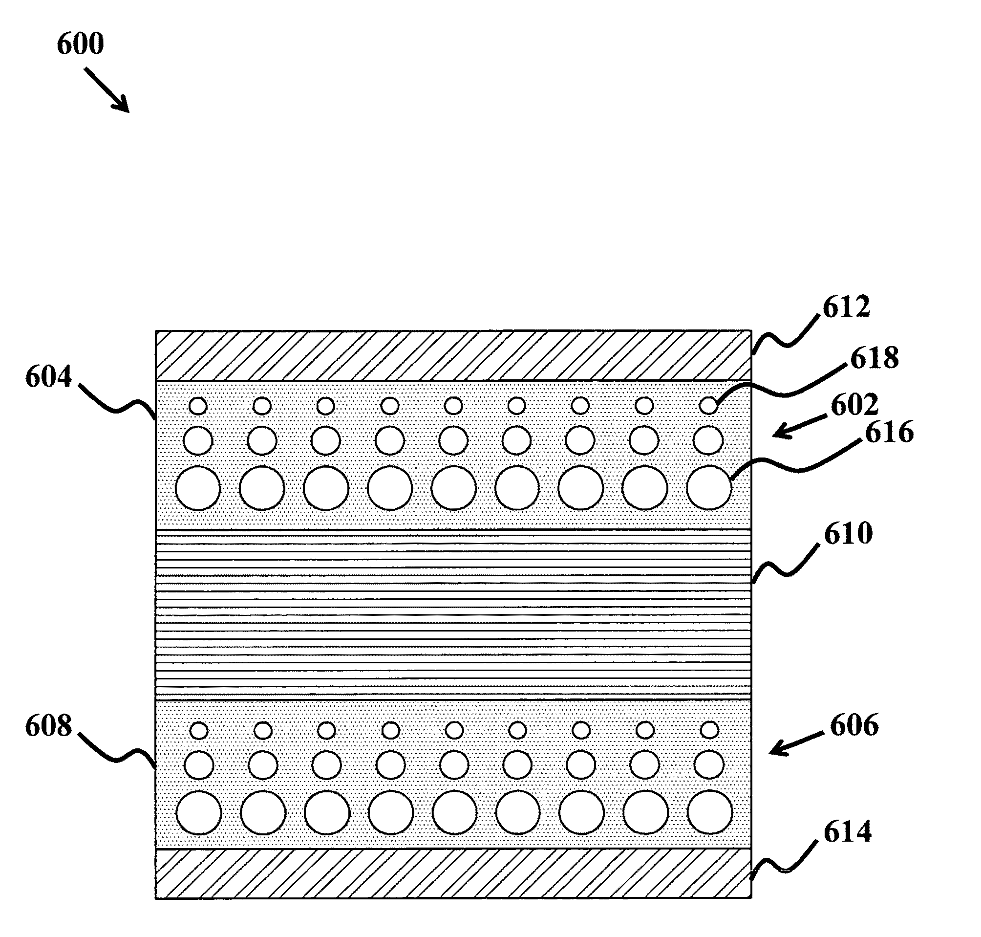
[0009]In another aspect of the invention, a plurality of the QCS are arranged between the first electrode and the second electrode in a gradient pattern according to features that can include a size of the QCS or a material of the QCS. Additionally, a relatively large size the QCS in the gradient can include a quantum dot quantum well, nanowire and bulk material. According to this aspect a relatively large size QCS in the gradient includes a material having a first work function and the relatively small QCS in the gradient includes a second work function.
[0010]According to one aspect of the invention, a plurality of the QCS is arranged according to size, where a relatively large size of at least one QCS is surrounded by an array of relatively small size QCS. In this aspect, the relatively large size QCS can be a quantum dot, quantum well, nanowire or bulk material. Further, the relatively large size QCS includes a material having a first work function and the relatively small size QCS includes a second work function.
[0011]In another aspect of the invention, the QCS are arranged by material, where a material with a high work function is surrounded by an array of relatively low work function QCS.
[0012]In another aspect of the invention, the QCS are arranged by material, where a material with a low work function is surrounded by an array of relatively high work function QCS.

Problems solved by technology

Existing energy storage devices have many disadvantages, including low energy storage density, slow charge / discharge performance, and high rates of degradation.
For example, the low storage density in existing batteries typically requires design of large and heavy devices to store a sufficient amount of energy.
The size and weight requirements can reduce the performance of devices that a battery is powering, such as in hybrid or electric vehicles.
Batteries have low storage density due to the large size and weight of the ions stored in the batteries.
Transporting the ions in existing batteries also causes slow charge and discharge performance.
Furthermore, the reliance of existing batteries on ionic transport causes high degradation rates of the batteries.
However, energy storage in a capacitor can be limited by the device geometry (e.g., 2-D capacitor plates having limited area), and batteries can have a slow response time due to the ion motion inherent in electrochemical reactions.

Method used


Image

  • Quantum dot ultracapacitor and electron battery
  • Quantum dot ultracapacitor and electron battery
  • Quantum dot ultracapacitor and electron battery

Examples


Embodiment Construction

[0028]Although the following detailed description contains many specifics for the purposes of illustration, anyone of ordinary skill in the art will readily appreciate that many variations and alterations to the following exemplary details are within the scope of the invention. Accordingly, the following preferred embodiment of the invention is set forth without any loss of generality to, and without imposing limitations upon, the claimed invention.

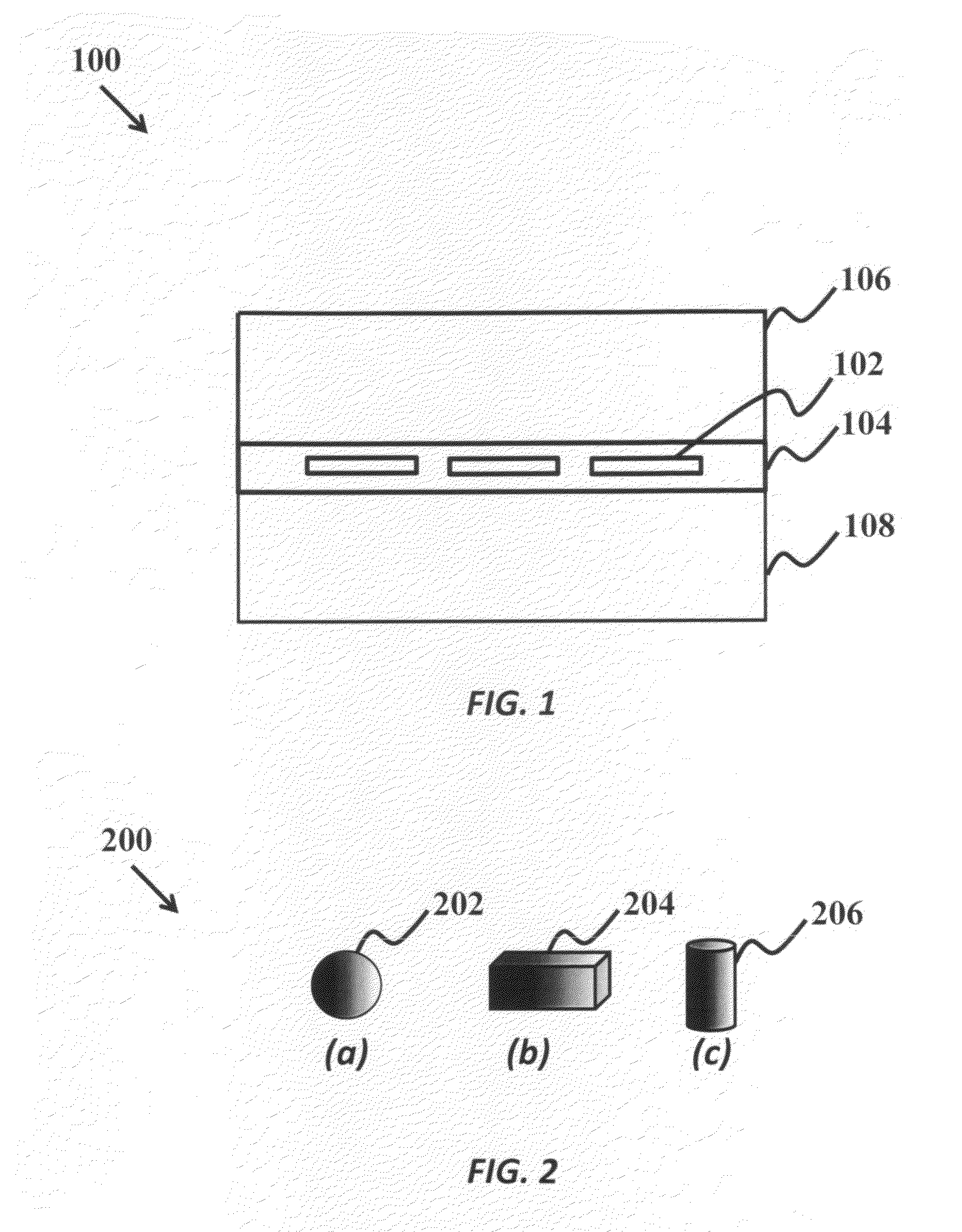
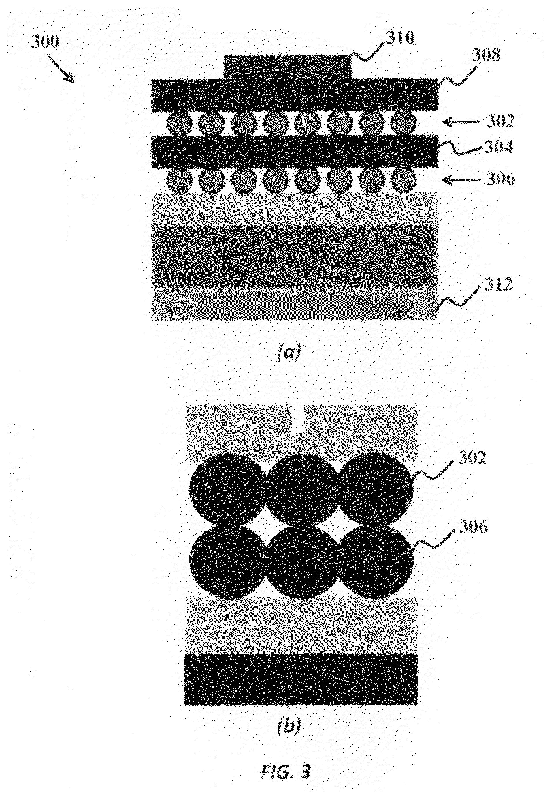
[0029]The present invention is directed to solid-state energy storage devices that are able to overcome the above disadvantages of existing energy storage devices. A device of the present invention includes one or more quantum confinement structures (QCS) embedded in a dielectric material or disposed on the surface of the dielectric material and is enclosed by conductive electrodes, such as two or more metal electrodes. When the electrodes are charged, at least some of the charge is transferred to the QCS. Further, the electrode charge in...


PUM

PropertyMeasurementUnit
dielectric constantaaaaaaaaaa
thicknessaaaaaaaaaa
thicknessaaaaaaaaaa

Abstract

The present invention provides a solid-state energy storage device having at least one quantum confinement species (QCS), where the QCS can include a quantum dot (QD), quantum well, or nanowire. The invention further includes at least one layer of a dielectric material with at least one QCS incorporated there to, and a first conductive electrode disposed on a top surface of the at least one layer of the dielectric material, and a second conductive electrode is disposed on a bottom surface of the at least one layer of dielectric material, where the first electrode and the second electrode are disposed to transfer a charge to the at least one QCS, where when an electrical circuit is disposed to provide an electric potential across the first electrode and the second electrode, the electric potential discharges the transferred charge from the at least one QCS to the electrical circuit.

Description

CROSS-REFERENCE TO RELATED APPLICATIONS[0001]This application is cross-referenced to and claims the benefit from U.S. Provisional Application 61 / 205,459 filed Jan. 16, 2009, and to U.S. Provisional Application 61 / 211,746 filed Apr. 1, 2009, which are hereby incorporated by reference.FIELD OF THE INVENTION[0002]The invention relates generally to energy storage devices. More particularly, the invention relates to solid state capacitors and batteries.BACKGROUND[0003]Energy storage is a crucial component of a large number and variety of electronic devices, particularly for mobile devices and vehicles. Energy storage devices include capacitors, which store charge for later discharge through a circuit, and batteries, which rely on ions and chemical reactions to store and release energy. Existing energy storage devices have many disadvantages, including low energy storage density, slow charge / discharge performance, and high rates of degradation. For example, the low storage density in exis...

Claims


Application Information

Patent Timeline
Patent Type & Authority Applications(United States)
IPC IPC(8): H01M4/02
CPCB82Y10/00B82Y30/00H01L28/40H01L29/127H01L29/92H01L27/04
Inventor HOLME, TIMOTHY P.PRINZ, FRIEDRICH B.
Owner THE BOARD OF TRUSTEES OF THE LELAND STANFORD JUNIOR UNIV
Learn More