
Mold for producing silica crucible

a technology of silica crucible and mold, which is applied in the field of mold, can solve the problems of inability to produce such a small-diameter thinned portion in the production process, the upper part of the silica crucible becomes small, and the thickness of the silica crucible becomes thin, so as to achieve the effect of reducing the cost of material

Active Publication Date: 2010-07-15
SUMCO CORP
View PDF2 Cites 6 Cited by
  • Summary
  • Abstract
  • Description
  • Claims
  • Application Information

AI Technical Summary

Benefits of technology

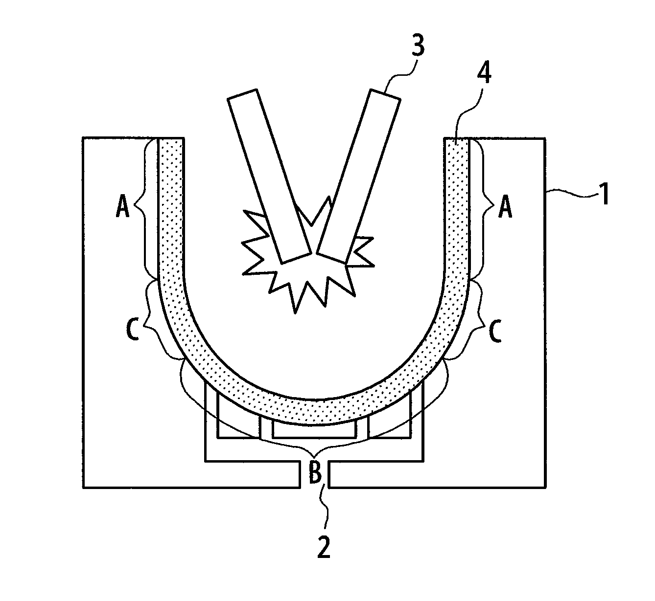
[0023]The invention is developed in the light of the above situation and is to provide a mold for producing a silica crucible capable of reducing a portion obliged to be removed by cutting due to the small-diameter thinning in the upper part of the silica crucible to effectively reduce the material cost.
[0030]According to the invention, it is possible to reduce a portion to be removed by cutting due to the small-diameter thinning as compared with the conventional technique, and as a result, the material cost and hence the product cost can be reduced.
[0031]Furthermore, according to the invention, it is possible to recycle as a rim member a small-diameter thinned portion inevitably formed in the upper portion of the silica crucible during the production of the silica crucible and then removed by cutting, so that extra cost is not required for the production of the rim member.

Problems solved by technology

A cause of forming such a small-diameter thinned portion is that heat easily escapes at the opening portion of the mold and the silica or quartz powder is not completely melted by arc heating, and hence the outer diameter at the upper part of the silica crucible becomes small and the thickness thereof becomes thin.
The formation of such a small-diameter thinned portion is unavoidable in the production process.
However, the formation of the small-diameter thinned portion cannot be completely prevented.
Therefore, it is still difficult to produce a good silicon single crystal ingot by the pulling method even when such a silica glass crucible is used.
Also, this technique entails such a structure that a ring-shaped member made of a different material is embedded in a crucible, so that there is a fear that when a carbon ring is embedded in a silica glass, strain is caused due to the difference in the thermal expansion coefficient between both the members.
In order to solve the problem, a mold for exclusive use for a product having a low height may be provided, but when the number of silica crucibles produced is small or the like, there is a disadvantage that the production cost of a new mold and related costs become significant.
As described above, when the silica crucible is produced by the rotating mold method, the formation of the small-diameter thinned portion is unavoidable, so that a silica crucible having a crucible height higher by the small-diameter thinned portion than a height of a product specification is produced and then the small-diameter thinned portion is removed by cutting to obtain a product (silica crucible) through usual steps.
When the diameter of the crucible is made larger, a portion obliged to be removed by cutting is also increased due to the small-diameter thinning, which causes a serious problem in terms of the material cost, and hence the production cost.

Method used


Image

  • Mold for producing silica crucible
  • Mold for producing silica crucible
  • Mold for producing silica crucible

Examples


example 1

[0067]In the invention, it is possible to reduce the silica or quartz powder by an amount corresponding to the volume of the rim member. That is, the amount of silica or quartz powder reduced can be approximated by the following equation:

[0068]Amount of silica or quartz powder reduced ≈(weight of rim member / specific gravity of rim member) x bulk specific gravity of silica or quartz powder

[0069]Therefore, the amount of silica or quartz powder reduced can be calculated according to the weight of the rim member used as shown in Table. 1.

TABLE 1WeightSpecificBulk specific gravityAmount of silica orof rimgravity ofof silica or quartzquartz powdermember (kg)rim memberpowderreduced (kg)102.21.235.682.21.234.562.21.233.442.21.232.222.21.231.112.21.230.6

[0070]In fact, when a 32 inch silica crucible having an outer diameter of 810 mm and a thickness of 15 mm is produced with a mold having a structure according to the invention as shown in FIG. 3, a rim member having a weight of 8.3 kg is disp...


PUM

PropertyMeasurementUnit
Weightaaaaaaaaaa
Weightaaaaaaaaaa
Weightaaaaaaaaaa

Abstract

In a mold for use in the production of a silica crucible, a cylindrical rim member is engagedly supported through hooks to an inner side of an upper opening portion of the mold corresponding to an upper part of a silica crucible and an outer diameter of the rim member is smaller than an inner diameter of the mold but larger than an inner diameter of the silica crucible.

Description

BACKGROUND OF THE INVENTION[0001]1. Field of the Invention[0002]This invention relates to a mold suitable for use in the production of a silica crucible used when producing a silicon single crystal ingot by a pulling method such as the CZ method or the like.[0003]Particularly, the invention is directed to advantageously reduce the amount of silica or quartz powder used when producing a silica crucible by a rotating mold method.[0004]2. Description of the Related Art[0005]Recently, the use of a silicon wafer as a substrate for semiconductor devices has increased rapidly. Such a silicon wafer is usually produced by forming a silicon single crystal ingot and then slicing it.[0006]Such a silicon single crystal ingot is generally produced, for example, by a pulling method such as the CZ method or the like. Also, a silica crucible is used for pulling the silicon single crystal.[0007]A typical method of producing a silica crucible is known as the rotating mold method. The rotating mold met...

Claims


Application Information

Patent Timeline
IPC IPC(8): B29C33/44
CPCC03B19/095C30B35/002C30B29/06C30B15/10
Inventor YOSHIOKA, TAKUMAMORIKAWA, MASAKI
Owner SUMCO CORP
Learn More