
Hydrogen Sensor

a technology of hydrogen sensor and sensor, applied in the field of hydrogen sensor, can solve the problems of small change in reflectance, explosion risk, and complicated structur

Inactive Publication Date: 2010-07-15
ATSUMITEC CO LTD +1
View PDF4 Cites 1 Cited by
  • Summary
  • Abstract
  • Description
  • Claims
  • Application Information

AI Technical Summary

Benefits of technology

[0009]In order to solve the above-mentioned problem, the present invention provides a hydrogen sensor comprising a substrate, a thin film layer formed over the substrate, a buffer layer formed over the thin film layer, and a catalyst layer formed over the buffer layer, which, by being contacted by hydrogen gas in an atmosphere, hydrogenates the thin film layer, thereby changing optical reflectance of the thin film layer, wherein the buffer layer contains a constituent that combines with a constituent of the thin film layer which diffuses from the thin film layer into the catalyst layer, thereby restraining oxidation of the catalyst layer.
[0012]More specifically, the thin film layer may be formed of a magnesium-nickel alloy, a magnesium-titanium alloy, a magnesium-niobium alloy, a magnesium-cobalt alloy or a magnesium-manganese alloy, for example. The thin film layer formed of such substance can more quickly undergo reversible hydrogenation.
[0013]When the thin film layer is formed of a magnesium alloy or magnesium, the buffer layer is formed to contain a constituent that combines with magnesium that diffuses from the thin film layer into the catalyst layer, thereby restraining the oxidation of the catalyst layer attributed to the magnesium.
[0018]In the hydrogen sensor structured as described above, even if the buffer layer prevents the constituent of the catalyst layer from diffusing in the thin film layer, the above constituent of the thin film activation layer diffuses in the thin film layer and promotes the hydrogenation and dehydrogenation of the thin film layer, resulting in a further improved hydrogen detection sensitivity of the hydrogen sensor. The thin film activation layer may be formed of either a single constituent (one metal element or the like, for example) or a plurality of constituents (an alloy, for example), as long as it contains a constituent which, by being contacted by hydrogen, hydrogenates the thin film layer, thereby changing the optical reflectance of the thin film layer.

Problems solved by technology

There is, however, a risk of explosion if hydrogen gas leaks into an atmosphere.
Consequently, a hydrogen gas leak detector using this semiconductor sensor has a drawback that it is complicated in structure.
Thus, there is a risk that the oxidation of the catalyst layer entails oxidation of the thin film layer, resulting in a smaller change in reflectance, and therefore, a decrease in leaked hydrogen gas detection sensitivity of the thin film layer (which means deterioration of the hydrogen sensor).

Method used


Image

  • Hydrogen Sensor
  • Hydrogen Sensor
  • Hydrogen Sensor

Examples


first embodiment

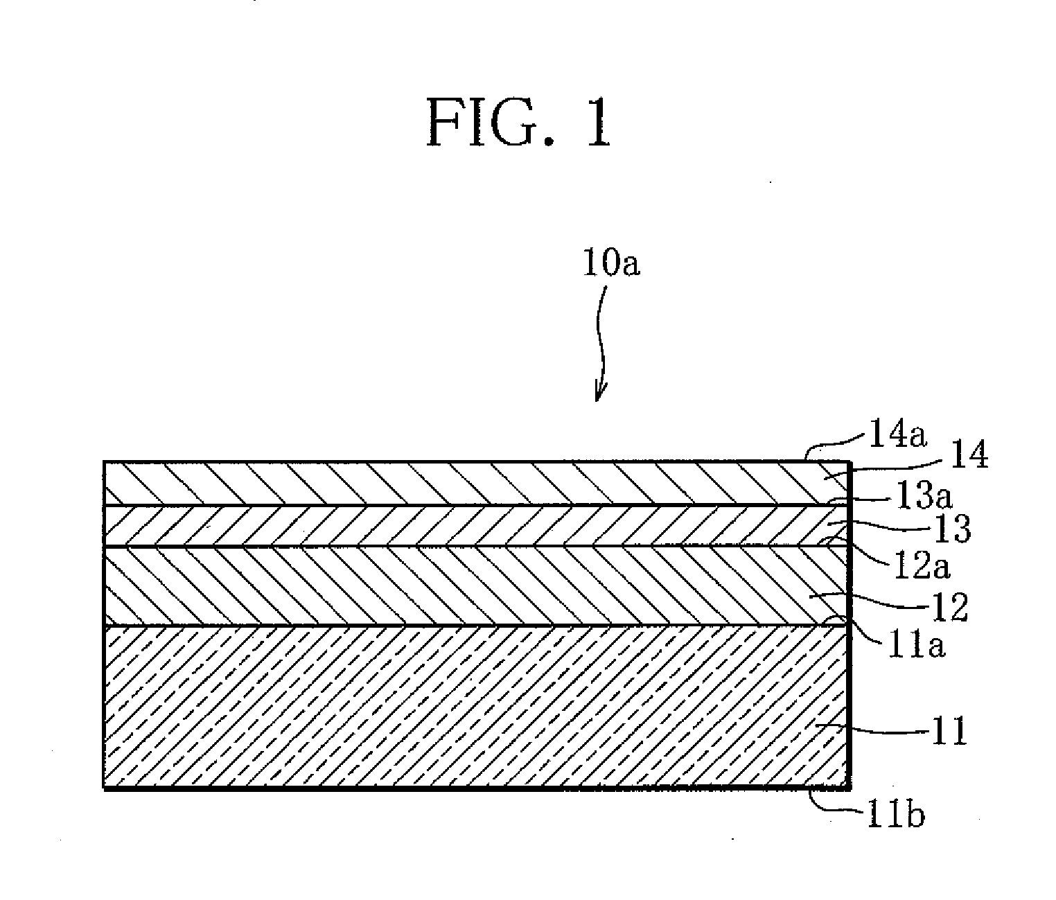
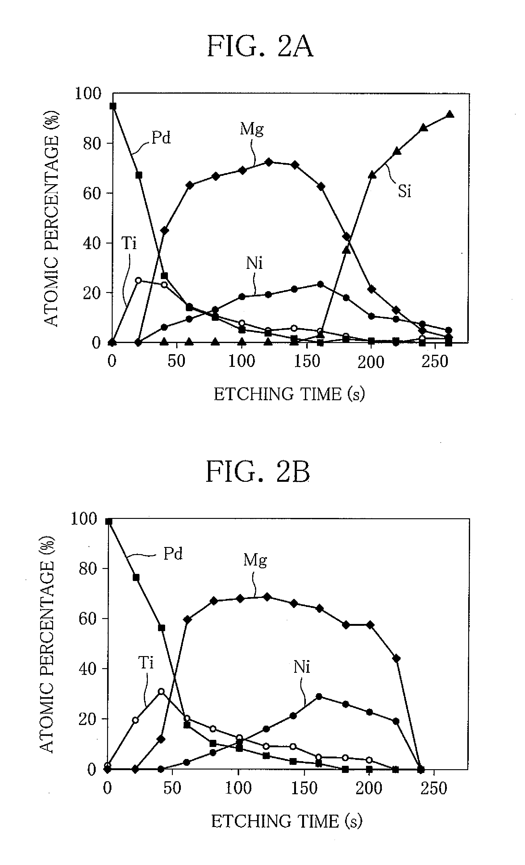
[0034]First, referring to FIGS. 1 to 4B, a hydrogen sensor according to the present invention will be described in details.

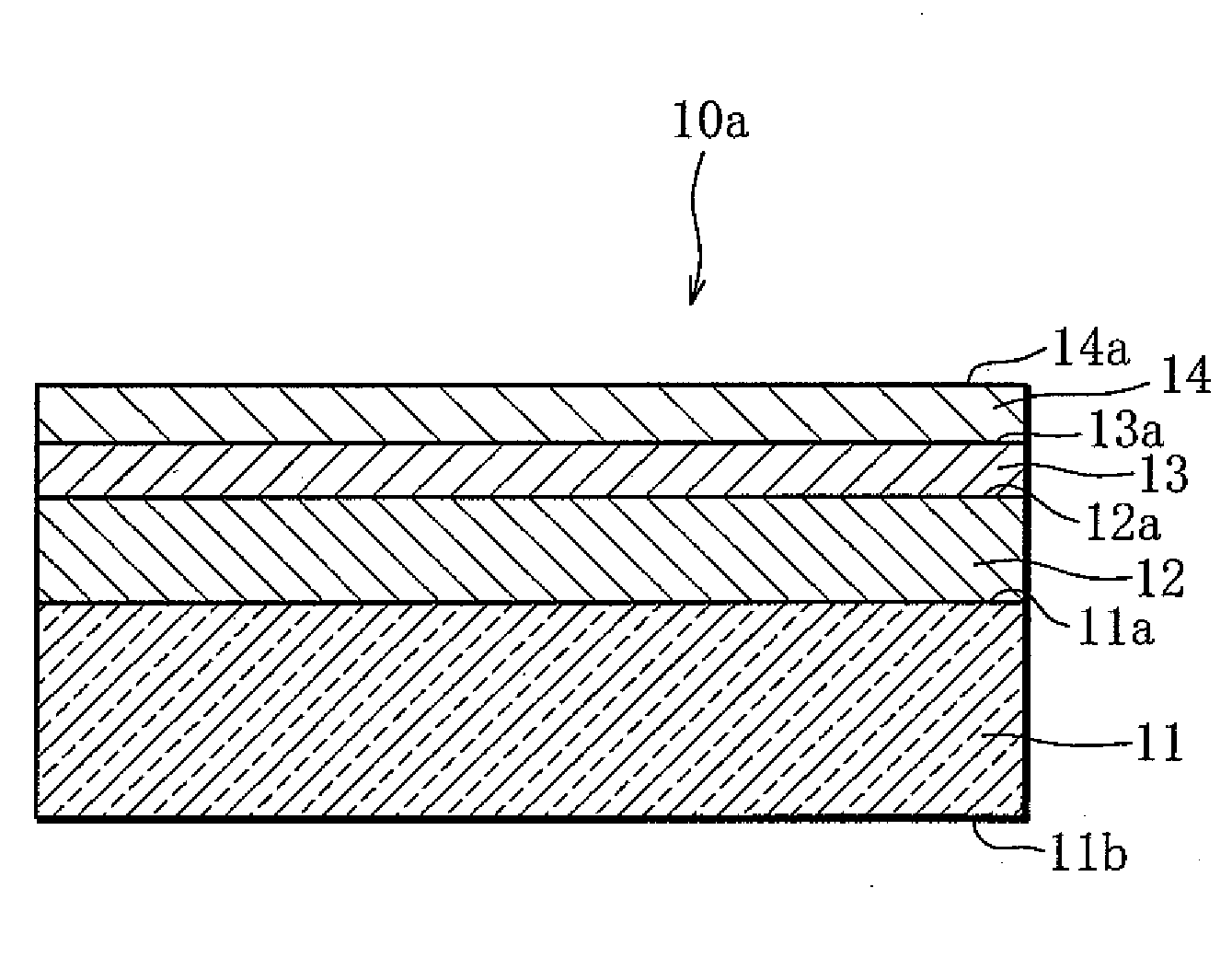
[0035]The hydrogen sensor 10a shown in FIG. 1 includes a substrate 11 of glass. On the surface 11a of the substrate 11, a thin film layer 12 of elemental composition MgNix (0≦x12a of the thin film layer 12, a buffer layer 13 of titanium (Ti) is formed. Further, on the surface 13a of the buffer layer 13, a catalyst layer 14 of palladium (Pd) is formed. Here, the thickness of the thin film layer 12 is 40 nm, the thickness of the buffer layer 13 is 2 nm, and the thickness of the catalyst layer 14 is 4 nm.

[0036]The buffer layer 13 less than 1 nm in thickness results in a reduction in the amount of titanium (Ti) or the like diffusing from the buffer layer 13 into the catalyst layer 14, and therefore difficulty in preventing the oxidation of the catalyst layer 14. The buffer layer 13 more than 5 nm in thickness, on the other hand, makes it difficult for a constituent ...

second embodiment

[0056]Next, referring to FIG. 6, a hydrogen sensor which is a variation of the second embodiment will be described in detail, where constructional elements similar in function to those of the preceding embodiments will be assigned the same reference marks, while the description of those constructional elements will be omitted.

[0057]The hydrogen sensor 10c shown in FIG. 6 is formed by further interposing a second thin film activation layer 15s between the buffer layer 13 and the thin film layer 12 in the structure of the hydrogen sensor 10a according to the first embodiment. The second thin film activation layer 15s is formed to contain palladium (Pd). In the hydrogen sensor 10c, palladium (Pd) diffuses from the second thin film activation layer 15s into the thin film layer 12 and promotes hydrogenation dehydrogenation of the thin film layer 12. Thus, in the hydrogen sensor 10c, while the buffer layer 13 prevents the oxidation of the catalyst layer 14 and the thin film layer 12, and ...


PUM

PropertyMeasurementUnit
thicknessaaaaaaaaaa
operating temperatureaaaaaaaaaa
depthaaaaaaaaaa

Abstract

In a hydrogen sensor (10a, 10b, 10c, 10d), a thin film layer (12) is formed over a substrate (11) and a buffer layer (13) is formed over the thin film layer (12). Further, over the buffer layer (13) is formed a catalyst layer (14) which, by being contacted by hydrogen gas, hydrogenates the thin film layer (12), thereby changing optical reflectance of the thin film layer (12). A constituent of the thin film layer (12) diffusing into the catalyst layer (14) combines with a constituent that has diffused from the buffer layer (13) into the catalyst layer (14), so that oxidation of the catalyst film layer (14) is prevented. Consequently, oxidation of the catalyst layer (14), etc. caused by repetition of hydrogenation of the thin film layer (12) is prevented, and therefore, decrease in hydrogen detection sensitivity of the hydrogen sensor (10a, 10b, 10c, 10d) is restrained.

Description

TECHNICAL FIELD[0001]The present invention relates to a hydrogen sensor for detecting hydrogen gas.BACKGROUND ART[0002]From a viewpoint of preventing carbon dioxide emissions into the atmosphere, hydrogen has been attracting attention as an energy source. There is, however, a risk of explosion if hydrogen gas leaks into an atmosphere. Thus, the development of a hydrogen sensor capable of quickly detecting leaked hydrogen gas has been being advanced. As such hydrogen sensor, a semiconductor sensor using tin oxide has been developed. The operating temperature of this semiconductor sensor is, however, as high as about 400° C. Thus, in using this semiconductor sensor, it is necessary to take a preventive measure against explosion. Consequently, a hydrogen gas leak detector using this semiconductor sensor has a drawback that it is complicated in structure.[0003]In this situation, there have been developed hydrogen sensors in which a thin film layer of a magnesium-nickel alloy or the like...

Claims


Application Information

Patent Timeline
Patent Type & Authority Applications(United States)
IPC IPC(8): G01N31/10G01N21/55G01N21/78G01N31/00G01N31/22
CPCG01N33/005G01N31/22B82Y30/00G01N21/783G01N2021/7773
Inventor UCHIYAMA, NAOKIYOSHIMURA, KAZUKI
Owner ATSUMITEC CO LTD
Learn More