
Multipurpose holdown

Active Publication Date: 2010-07-01
SIMPSON STRONG TIE +1
View PDF99 Cites 14 Cited by
  • Summary
  • Abstract
  • Description
  • Claims
  • Application Information

AI Technical Summary

Benefits of technology

[0008]The connector of the present invention improves on the prior art by combining a set of design features to achieve loads comparable to connectors made from much heavier sheet metal. Connectors made

Problems solved by technology

Connectors made from much heavier sheet metal are several times more expensive to make and are also more expensive to ship, not to mention relatively wasteful of both sheet metal in manufacturing and fuel in shipping.

Method used


Image

  • Multipurpose holdown
  • Multipurpose holdown
  • Multipurpose holdown

Examples


Embodiment Construction

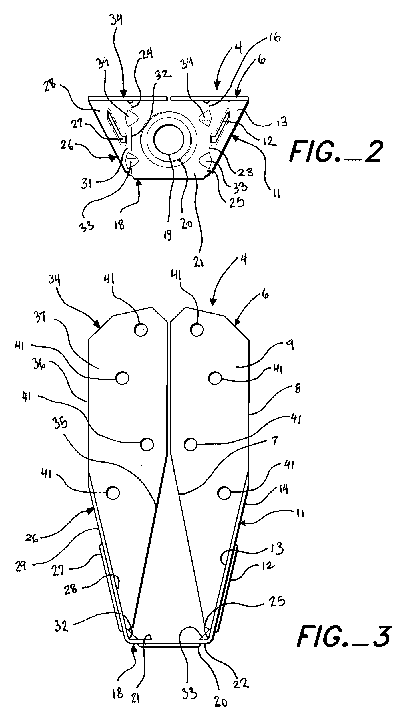
[0021]As shown in FIG. 8, the present invention is a building connection 1 that comprises an anchored structural member 2 attached to a sheet metal connector 4, an anchoring structural member 3 that hold an anchor member 5, the sheet metal connector 4 and the anchor member 5. The sheet metal connector 4 is fastened to the anchored structural member 2 and is anchored to the anchoring structural member 3 by the anchor member 5. The anchor member 5 is restrained by the anchoring structural member 3. The sheet metal connector 4 comprises a first back member 6, a first side member 11, a seat member 18, a second side member 26, and a second back member 34. The terminology “anchored” and “anchoring” for the structural members 2 and 3 is not intended to exclude the possibility of connecting a pair of the sheet metal connectors 4 of the present invention with an anchor member 5 that is held in tension between the paired sheet metal connectors 4, as in a floor-to-floor or purlin-to-purlin con...


PUM


Abstract

A connection made with a multi-purpose connector that can act as a holdown or tension tie and transfer tension, uplift, or lateral load, between a minimum nominal 2×4″ wood framing member and a ½″ diameter anchor. The anchor may be tied to a concrete foundation, another connector of the same type, a wood framing member, or other supporting members.

Description

BACKGROUND OF THE INVENTION[0001]This invention relates to a sheet metal connector for anchoring an anchored structural member to an anchoring structural member. The connector works in conjunction with a separate anchor member that is received by or is attached to the anchoring structural member and with fasteners for attaching the connector to the anchored structural member.[0002]Earthquake, hurricanes, tornadoes and floods impose forces on a building that can cause structural failure. To counteract these forces, it has become common practice to strengthen or add ties between the structural members of a building in areas where such cataclysmic forces may be imposed. For example: framed walls can be attached to the foundation rather than merely rest upon it; connections between the framed walls of each floor can be strengthened; and joists can be connected to both their headers and the walls that support the headers. One of the most common connectors designed for this application is...

Claims


Application Information

Patent Timeline
IPC IPC(8): F16B1/00
CPCE04B1/2604E04B2001/2644E04B2001/2684Y10T403/42F16B2200/67
Inventor VILASINEEKUL, KASHANE
Owner SIMPSON STRONG TIE
Learn More