
Actuator module with a sheathed piezoelectric actuator

Active Publication Date: 2010-07-01
ROBERT BOSCH GMBH
View PDF7 Cites 6 Cited by
  • Summary
  • Abstract
  • Description
  • Claims
  • Application Information

AI Technical Summary

Benefits of technology

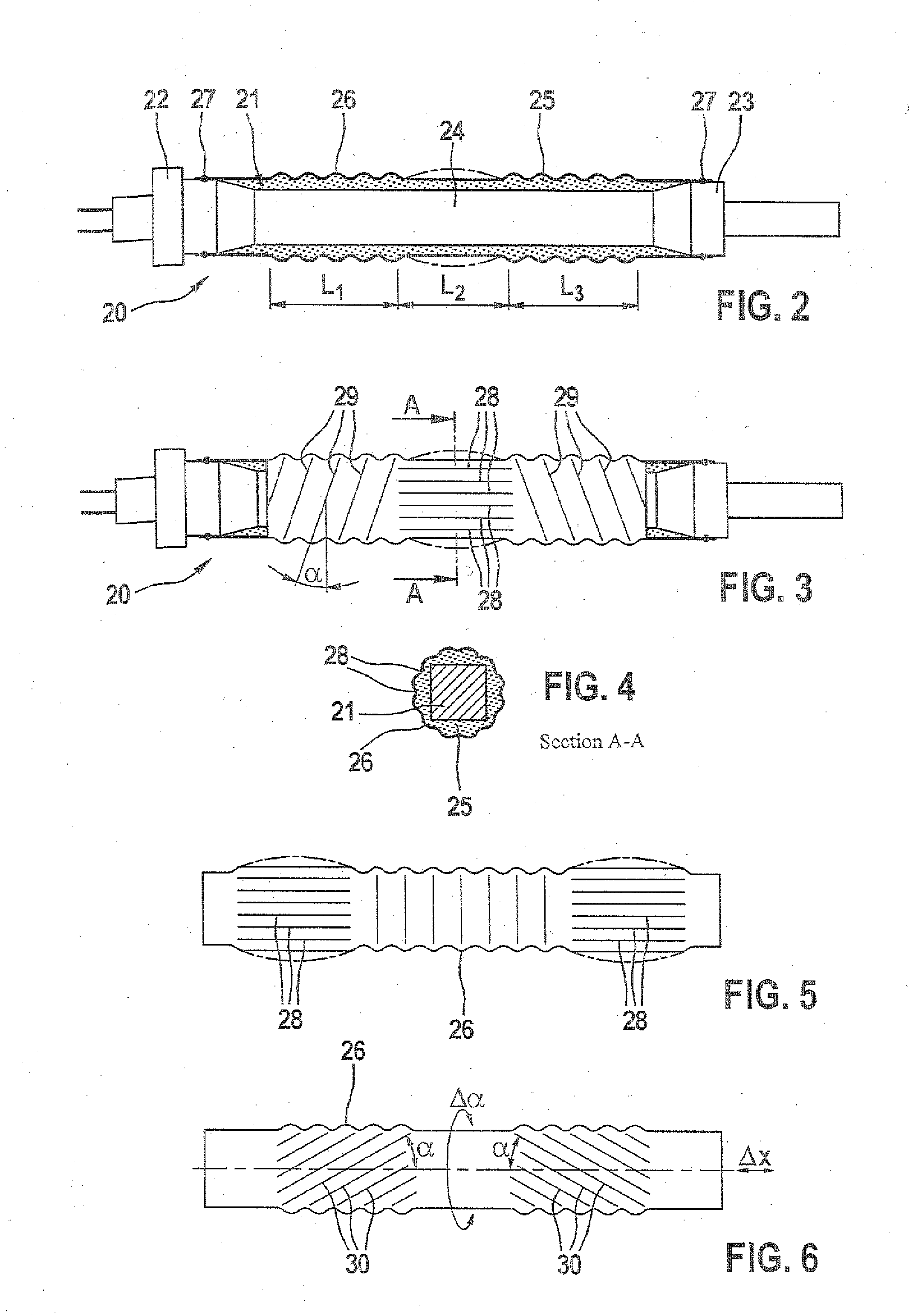
[0006]In addition to the requisite diffusion-proof sheathing of the piezoelectric actuator, the refinement according to the invention of the actuator module is advantageous in particular because the elastomer layer, lying beneath the sheath, can expand unhindered upon heating, without mechanically destroying the sheath from the internal pressure that occurs, for instance from cracks. Moreover, air bubbles and voids in the elastomer layer can be compacted by means of the invention without tearing of the sheath.
[0009]In this last proposed embodiment, the interstices between the telescoping tubes, joined one inside the other, can also be filled with elastomer, and as a result, advantageously, the diffusion length of the surrounding fluid is lengthened, and the diffusion area is reduced, in comparison with the elastomer layer lying on the piezoelectric actuator.
[0010]If smooth telescoping tubes are used as sheaths here, then compensation takes place of axial expansion between the telescoping tubes filled with elastomer; because of the relatively narrow gap between the telescoping tubes, the elastomer is subjected to strong shear stress, but it is almost impossible to compensate for radial expansion, for instance upon thermal expansion. With the advantageous disposition of grooves in accordance with the invention, compensation for both radial and axial expansion is thus made substantially easier.
[0011]The proposed grooves can advantageously also be axially extending longitudinal grooves, which then facilitate an axial thermal expansion of the piezoelectric actuator without the risk of damage to the sheath. On the other hand, the proposed longitudinal grooves may instead be radially extending transverse grooves, which absorb radial expansion of the piezoelectric actuator, thereby reducing the thrust stresses in the elastomer. However, the grooves can also be embodied as single- or multi-thread and clockwise and / or counterclockwise grooves extending at a predetermined angle to the longitudinal or transverse axis of the piezoelectric actuator, or a combination of all the embodiments of grooves proposed can be provided.
[0012]Particularly from the axial component of the orientation of the grooves, it can thus be assured in a simple way that the internal pressure of the elastomer layer can decrease upon a thermal expansion and will not damage the actuator module or the sheath. If there are remaining air bubbles or other remaining voids between the elastomer layer and the sheath, the longitudinal grooves can easily yield radially and compress the air, again without damaging the rest of the sheath.

Problems solved by technology

This is not attainable with the corrugated bellows known from the prior art, since that corrugated bellows remains radially rigid.

Method used


Image

  • Actuator module with a sheathed piezoelectric actuator
  • Actuator module with a sheathed piezoelectric actuator
  • Actuator module with a sheathed piezoelectric actuator

Examples


Embodiment Construction

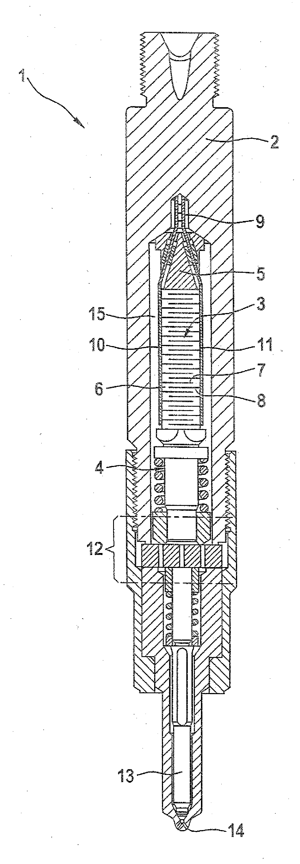
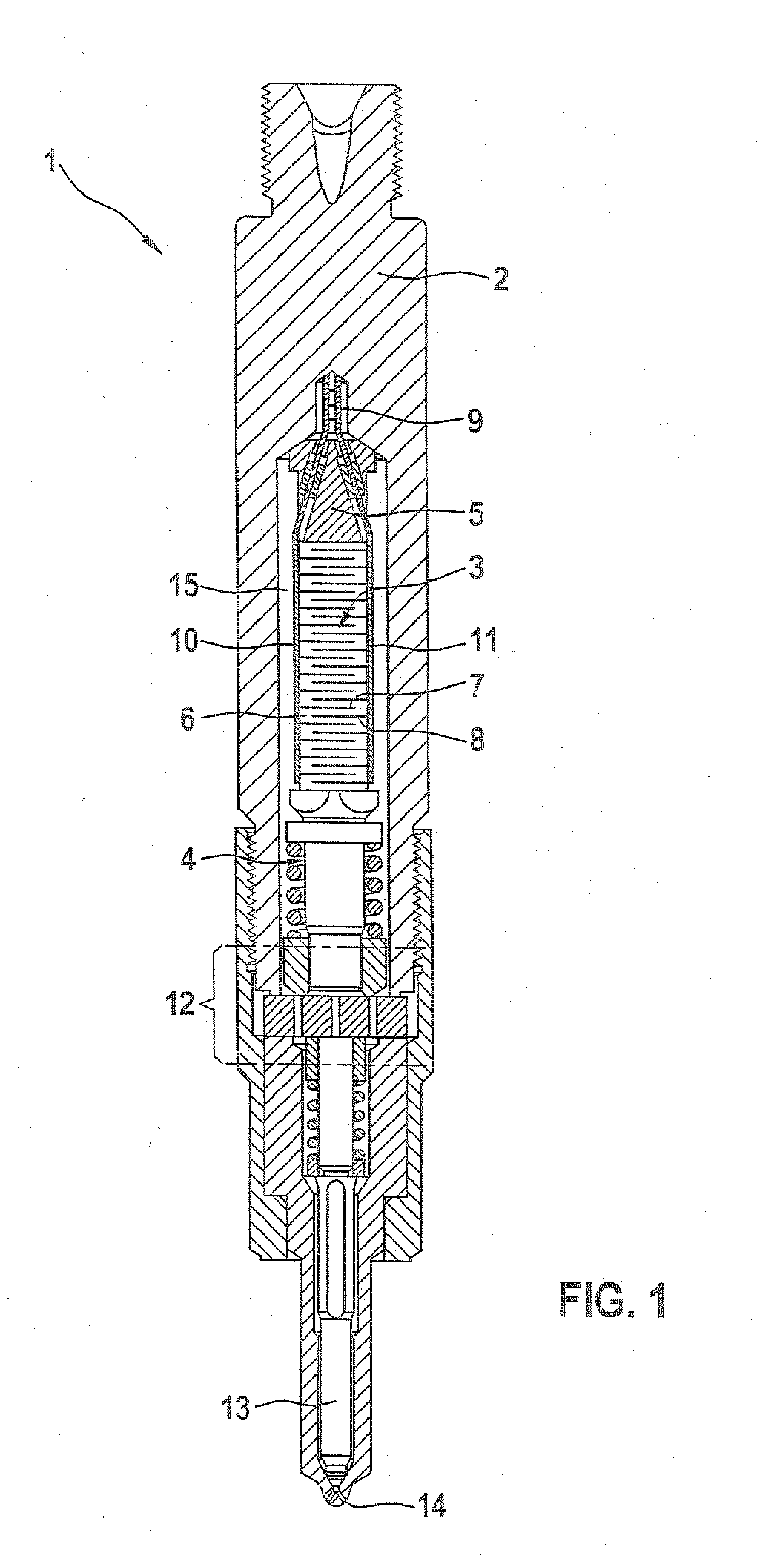
[0029]A piezoelectric injector 1 in accordance with the prior art, shown in FIG. 1 to explain the actuator module of the invention, essentially includes a holder body 2 and a piezoelectric actuator 3, which is located in the holder body 2 and has an actuator head 4 and an actuator foot 5. Between the actuator head 4 and the actuator foot 5, there is a plurality of elements 6, stacked one above the other, which each comprise piezoelectric layers of piezoelectric ceramic and inner electrodes 7 and 8 enclosing the piezoelectric ceramic.

[0030]The inner electrodes 7 and 8 of the elements 6 are contacted electrically via a plug part 9 with lead lines to outer electrodes 10 and 11. The piezoelectric actuator 3, which with other components, not shown in detail here, represents a so-called actuator module, is connected to a nozzle needle 13 via a coupler 12. By application of a voltage to the elements 6 via the inner electrodes 7 and 8 and by the resultant mechanical reaction, a nozzle openi...


PUM


Abstract

An actuator module including a piezoactuator, for example for a piezoinjector for metering fuel in an internal combustion engine, is proposed. The piezoactuator has piezoelements stacked one above another between an actuator head and an actuator foot and is provided with at least one elastomer layer enclosing the piezoelements. The elastomer layer is enveloped by a corrugated bellows or by telescopic tubes, composed of a material that is diffusion-impermeable with respect to a fuel to be metered by the piezoinjector. The corrugated bellows or the telescopic tubes have on their periphery grooves which can absorb expansions of the elastomer layer or of the piezoactuator.

Description

PRIOR ART[0001]The invention relates to an actuator module with a piezoelectric actuator having a sheath, as generically defined by the preamble to the main claims, which can be used for instance in a piezoelectric injector for chronologically and quantitatively precise metering of fuel in an internal combustion engine.[0002]One such piezoelectric injector essentially comprises a holder body and the piezoelectric actuator disposed in the holder body; the piezoelectric actuator has elements, stacked one above the other between an actuator head and an actuator foot, and each of the elements comprise piezoelectric layers enclosed by inner electrodes. The elements are constructed, using a material with a suitable crystalline structure (piezoelectric ceramic) for the piezoelectric layers, in such a way that upon application of an external voltage to the inner electrodes, a mechanical reaction of the elements ensues, which as a function of the crystalline structure and the regions of cont...

Claims


Application Information

Patent Timeline
IPC IPC(8): F02M63/00H01L41/053
CPCH01L41/083H01L41/053H10N30/88H10N30/50
Inventor HEINZ, RUDOLFKIENZLER, DIETERSCHAICH, UDO
Owner ROBERT BOSCH GMBH
Learn More