Lateral-flow porous membrane assay with flow rate control

a porous membrane and flow rate technology, applied in the direction of instruments, analysis using chemical indicators, bandages, etc., can solve the problems of dehydration or hypohydration, the continuous flow of commercial dipsticks, and serious consequences for dehydrated people, so as to reduce the continuity of the membrane structure, increase the amount of time, and increase the flow time

Inactive Publication Date: 2010-06-24
KIMBERLY-CLARK WORLDWIDE INC
View PDF12 Cites 82 Cited by
  • Summary
  • Abstract
  • Description
  • Claims
  • Application Information

AI Technical Summary

Benefits of technology

[0039]One embodiment of this invention involves using a laser to remove specific sections of one or more of the lateral flow membranes. To maintain test integrity, the laser intensity can be tuned so that only the membrane is removed and not the supporting backing card. The membrane can be removed in sections or patterns of laser cuts can be created. Examples of patterns include, but are not limited to dots, dashes, circles, triangles, other geometric shapes. Additionally, the laser can be dynamically tuned such that a three dimensional relief of a picture or complex pattern is achieved. The density and cross-sectional depth of these patterns can effectively control the rate of the flow of the fluid sample. In addition, the pattern and shape of the laser cuts can control the direction of fluid flow on the test strip.
[0040]FIG. 2 shows examples of patterns created on a laminated nitrocellulose test strip with a laser. Other methods of physically altering the membrane through mechanical means include punch dyes, vinyl cutters and others. Another embodiment of this invention utilizes printing techniques to apply hydrophobic materials to the lateral flow membrane material. The hydrophobic materials can be applied in sections or patterns much like the laser cut embodiment. Similarly, the pattern, the density, and the shape can control and alter flow rate and flow direction of the fluid. Additionally, the penetration depth of the hydrophobic ink into the membrane can change the rate of fluid flow.
[0041]Examples of the hydrophobic materials include but are not limited to commercial Sharpie® ink and hydrophobic polymers (e.g., polystyrene and polyvinyl chloride). An example of a permanent ink (e.g., Sharpie™ Ink) on nitrocellulose is depicted in FIG. 3. Yet another embodiment includes removing sections of the lateral flow membrane through chemical etching. An example of this methodology was previously described in two U.S. Patent Publications US 2006 / 0246597 A1, and US 2006 / 0246600 A1, the content of which are incorporated herein by reference, describing flow control and metering techniques, respectively.
[0042]In particular, one or more recessed regions are formed in the substrate by applying a solvent treatment. The solvent treatment is selected based on its particular dissolving capacity for the material used to form the membrane. For example, an alcohol-based solvent, such as methanol, may be used for nitrocellulose membranes. Upon contact with the solvent treatment, a recessed region is formed that may serve a variety of different functions relating to flow-rate control. The solvent treatment may be applied to the membrane using any of a variety of well-known application techniques. Suitable application techniques include, for example, standard lithography and photo resist technology, spraying, printing (e.g., inkjet, pad, etc.), pipetting, air brushing, metering with a dispensing pump, and so forth. In one particular embodiment, for example, the solvent treatment is applied using a dispensing and optional drying process commonly employed to form detection lines on lateral flow strips. Such a system could involve placing a sheet of the porous membrane on a dispensing machine and threading it through a rewind spindle. This may be accomplished using either a batch or continuous process. The dispensing machine delivers a precise volume of the solvent treatment in a straight line as the membrane passes beneath. The sheet then passes through a drier and is wound back on a spool for further processing. For instance, a lab-scale dispensing pump system for batch processes is available from Kinematic Automation, Inc. of Twain Harte, Calif. under the name “Matrix® 1600.”
[0043]The solvent treatment may also be applied in any amount effective to form a recessed region having the desired size and shape. The ultimate amount employed may depend on a variety of factors, including the dissolving capacity of the solvent for the membrane material, the speed of application, etc. Regardless of the manner in which it is formed, the recessed region generally acts as a flow-rate control mechanism for the lateral flow device. For example, the recessed region may block the flow of the fluid through the membrane until such time that the assay is initiated, such as by placing the membrane in fluid communication with another membrane. Alternatively, the recessed region is simply used to slow down or otherwise control the flow of fluid through the membrane. For example, a plurality of discrete recessed regions (e.g., dots) may be formed to reduce the continuity of the membrane structure. Thus, a fluid flowing through the membrane structure is forced to follow a tortuous pathway, which increases the amount of time for the fluid to reach the detection zone. Such an increased flow time may provide a variety of benefits, such as to promote uniform mixing and ensure that any analyte within a test sample has sufficient time to react with the desired reagents. For example, the time for the test sample to reach the detection zone may be at least about 1 minute, in some embodiments at least about 2 minutes, in some embodiments from about 3 or 5 minutes to about 8 or 10 minutes, and in some embodiments, from about 10 or 12 minutes to about 25-30 minutes.
[0044]Particular uses for the present invention, it is envisioned, may include any lateral flow assays in which timing is critical, such as ensuring a minimum time has elapsed before reading and interpreting the results. One such example is a dehydration test designed for inclusion in a personal care garment, such as a diaper, where precise monitoring of the test is not practical. For a dehydration indicator developed internally, the detection zone requires 5-10 minutes to stabilize and reach equilibrium after coming In contact with the urine sample. If the test is read prior to equilibrium, inaccurate results may be given. Thus, it would be useful to include one of these flow-rate control zones in between the detection zone and the sample observation-control zone such that the sample fluid would not react with the sample observation-control zone until 10 minutes after reaching the detection zone. In such an embodiment the user would be assured that the test is ready to read once the observation-control zone color has formed. The flow-rate control zones could also be used in between detection zones of a multi-analyte test in which the signal from the zones forms at different rates. In such situation, it would be advantageous that most or all of the signals develop at the same time, so as not to confuse the user. Otherwise, the user may assume the test is complete once one signal is formed and therefore miss the other signals that develop later.

Problems solved by technology

A balance of bodily fluids is achieved and maintained by matching the input and excretion of liquid from the body, and an imbalance in fluids can be linked to either dehydration or hypohydration.
Dehydration can be of particular concern for either the infirm, elderly, or infants, and can have serious consequences to a dehydrated person if not cared for properly.
Problems, however, persist for all the commercially available dipsticks.
A major problem is that the user has to read a change in color within a few brief minutes after dipping in the sample because the color development is not stable under test conditions.
The signals that one may observe outside of a limited time window time window are often inaccurate, hence normally invalid.
This situation may not be a problem for a test that a user can constantly monitor; however, it becomes a problem when constant monitoring of the test is not feasible and sample introduction time is uncertain.
For instance, it is difficult, if not impossible, to predict accurately when a baby or incontinent adult will urinate to provide a sample for an assay device in a diaper or other personal care product.
However, conventional reagent strips for USG measurement suffer from major shortcomings, particularly for over-the-counter and point-of-care markets.
For instance, conventional reagent strips have a limited reading window because the signal produced by such strips begins to change only a short period of time after sample application.
Unless the strips are analyzed shortly after application of the sample, the signal change can lead to erroneous test results.
Multiple urine insults can lead to erroneous test results making such strips unsuitable for applications in absorbent articles where multiple urine insults cannot be controlled.
Finally, conventional reagent strips do not provide a way for a user to know if the test has been performed correctly or if enough sample has been applied.
Thus, an unsatisfied need exists for an assay device that can provide such assurance to caregivers in a cost effective way.

Method used


Image

  • Lateral-flow porous membrane assay with flow rate control
  • Lateral-flow porous membrane assay with flow rate control
  • Lateral-flow porous membrane assay with flow rate control

Examples


example 1

Preparation of Components:

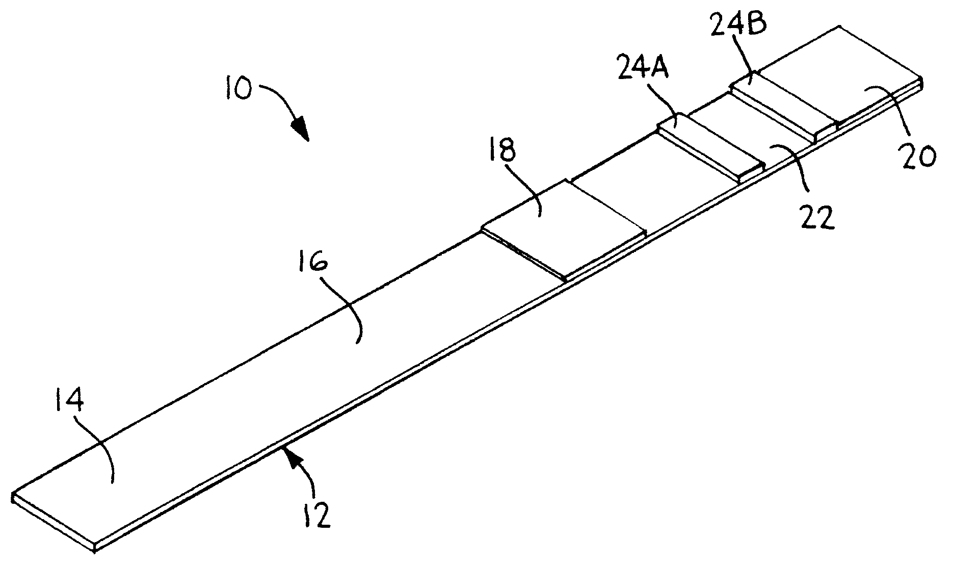
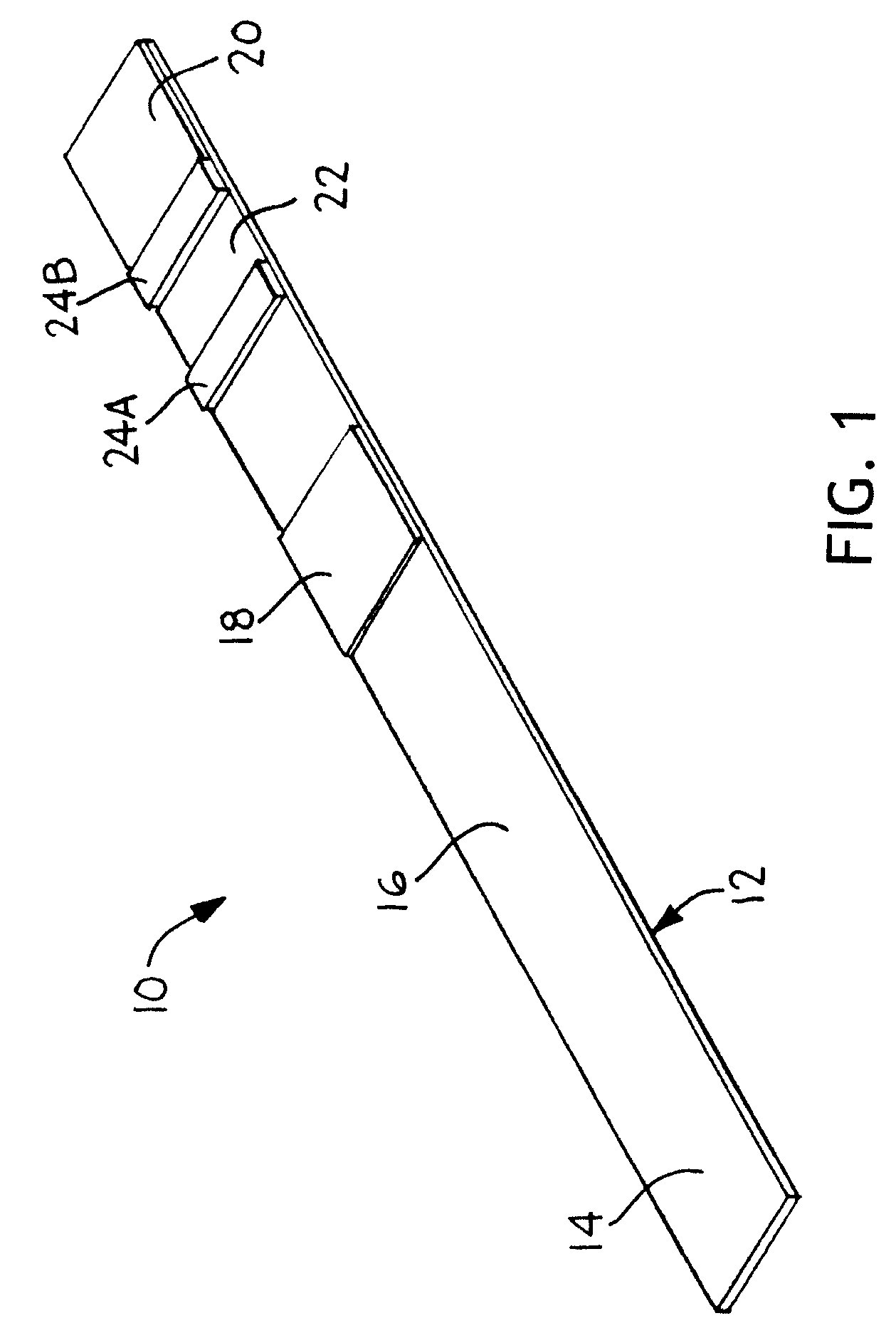
[0049]An 81 mm×300 mm Mylar backing card is laminated with 50 mm wide nitrocellulose membrane from Millipore. The distal end of the card is laminated with a 20 mm wide porous membrane from Millipore with a high liquid capacity that serves as an absorptive sink. The absorptive sink is positioned in fluid contact with the nitrocellulose membrane, with a total overlap zone of 3 mm. A 25 mm wide glass fiber pad from Millipore is laminated to the proximal end of the card and is in fluid contact with the nitrocellulose membrane with a total overlap zone of about 3 mm. The glass fiber serves as both the sample deposition zone and the conjugate pad. The conjugate is dispensed into three discrete bands on the conjugate pad with a liquid handling system from BioDot prior to assembly of this device. The conjugate consists of a C-reactive protein (CRP) monoclonal antibody conjugated to a gold label, with optical density 3.3. The detection zone contains a CRP antibody a...

example 2

Preparation of Components:

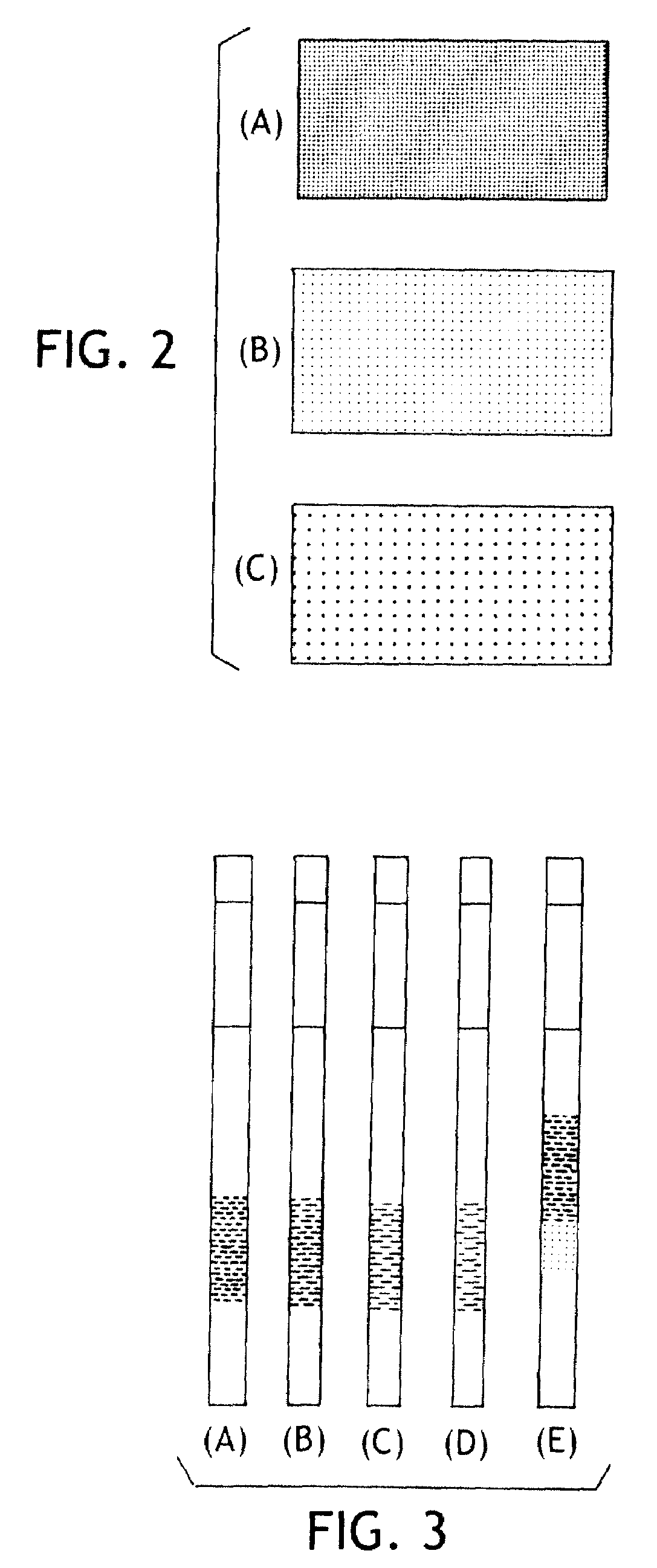
[0052]A 2 cm×30 cm piece of cellulose pad from Millipore Co. is soaked with 5 ml of polyacrylic sodium salt that is titrated to pH of 8.1 with 1N HCl. The pad is air-dried overnight to make a buffer pad. A 10 cm×10 cm piece of Biodyne Plus Nylon membrane from Pall Co. is soaked in a 30 ml of bromothymol blue aqueous solution (0.1 mg / ml) for 10 minutes and air-dried overnight to make a test pad. A 10 cm×10 cm piece of Biodyne Plus membrane is soaked with an aqueous solution containing bromocresol green (0.2 mg / ml) and citric acid (2 mg / ml) for 10 minutes and air-dried overnight to make a control test pad.

Assemble the Device with a 3 mm Wide Flow-Rate Control Zone:

[0053]On an 8 cm×30 cm supporting plastic card was laminated with a 5 mm wide strip of Biodyne B membrane. 2 cm from the edge of the card to make a flow-rate control zone. A 6 mm wide strip of a cellulose wicking pad was laminated on the card with a 1 mm overlap with the Biodyne B membrane on one si...


PUM

PropertyMeasurementUnit
lengthaaaaaaaaaa
lengthaaaaaaaaaa
areaaaaaaaaaaa

Abstract

Various modifications to a porous substrate, such as employed in lateral flow assay devices, to regulate or modify the flow rate and/or flow path pattern of a fluid through the porous substrate is described. The lateral flow assay device has a porous substrate matrix in fluid communication with a flow-rate control zone having a number of flow-rate control devices arranged as features in or on a substrate surface or laminates thereof in a body. The flow-rate control devices may include: a density gradient, porosity gradient, ion affinity gradient, micro-channels, and combinations thereof.

Description

FIELD OF INVENTION[0001]The present invention relates to fluidic control devices and channels as employed in a porous membrane or substrate. In particular, the invention describes alterations of a lateral flow substrate or membranes to regulate and modify fluid flow rate and patterns for certain assay formats.BACKGROUND[0002]Dehydration is the depletion of fluids and associated electrolytes from the body. Normally, a person's daily, total fluid amount is regulated to be within about ±0.02% of body weight, and water in the body may comprise approximately 63% of the entire body mass. A balance of bodily fluids is achieved and maintained by matching the input and excretion of liquid from the body, and an imbalance in fluids can be linked to either dehydration or hypohydration. Dehydration can be of particular concern for either the infirm, elderly, or infants, and can have serious consequences to a dehydrated person if not cared for properly. Loss of body fluids in amounts of less than...

Claims


Application Information

Patent Timeline
Patent Type & Authority Applications(United States)
IPC IPC(8): G01N33/18G01N33/48A61F13/534G01N33/53
CPCA61F13/42Y10T428/18G01N33/558G01N33/54386G01N33/54388
Inventor SONG, XUEDONGFEASTER, SHAWN R.TAKEUCHI, JAMES M.YANG, KAIYUAN
Owner KIMBERLY-CLARK WORLDWIDE INC
Why Eureka
Try Eureka