Eureka AIR delivers breakthrough ideas for toughest innovation challenges, trusted by R&D personnel around the world.

Navigation arm system and methods

Inactive Publication Date: 2017-10-26
SYNAPTIVE MEDICAL INC
View PDF4 Cites 141 Cited by
  • Summary
  • Abstract
  • Description
  • Claims
  • Application Information

AI Technical Summary

Benefits of technology

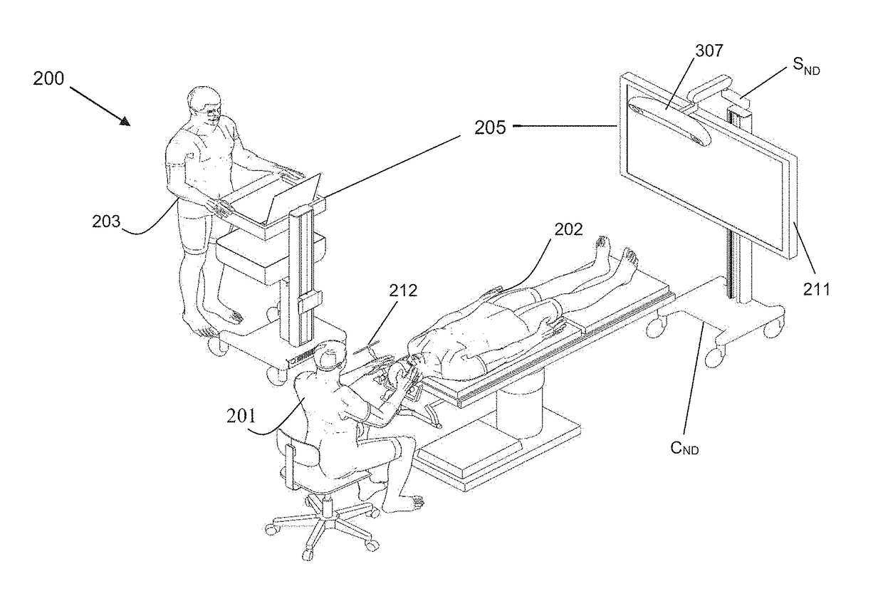
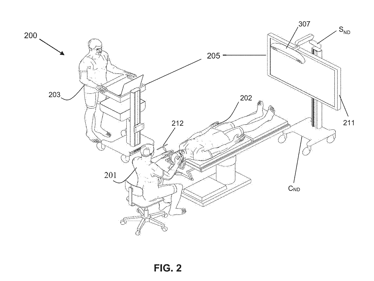
The present patent discloses a navigation arm system and method for accurately and stably positioning a navigation device, such as a camera, in a navigation system. The system includes an arm assembly with first and second arm linkages that increase the imaging volume over the related art and facilitate positioning the navigation device within an optimal measurement volume. The arm assembly is connected to a navigation display cart and a locking mechanism is used to maintain the position of the arm assembly. The navigation arm system provides more degrees of freedom and ensures correct tracking of tracking features. The cart includes a frame with wheels and a conduit for accommodating cables and wires. The system also includes a tracking camera attached to the arm and a display mounted on the cart for easy viewing. The technical effects of the present patent include increasing the measurement volume, optimizing the position of the navigation device, and maintaining the resolution of tracking markers.

Problems solved by technology

In the related art, conventional navigation carts for medical procedures create many hazards in a medical procedure room, such as an operating room, including tripping hazards from cables, tipping hazards from equipment stands or towers, and general hazards associated with clutter because of too many equipment pieces being present in the room.
In addition, challenges experienced in the related art also include inaccuracies involving navigation systems and navigation devices, e.g., the inability to accurately orient a surgical tool having attached passive markers by using an infrared (IR) camera.
Detection of surgical tools tends to fail, depending on an operation room environment, a test set-up, and a patient position, such as a prone or a supine position, etc.
In the limited space of an operating room, orienting the IR camera in a way that optimizes communication is difficult.

Method used


Image

  • Navigation arm system and methods
  • Navigation arm system and methods
  • Navigation arm system and methods

Examples


Embodiment Construction

[0076]As used herein, the phraseaccess port” refers to a cannula, conduit, sheath, port, tube, or other structure that is insertable into a subject, in order to provide access to internal tissue, organs, or other biological substances. In some embodiments, an access port may directly expose internal tissue, for example, via an opening or aperture at a distal end thereof, and / or via an opening or aperture at an intermediate location along a length thereof. In other embodiments, an access port may provide indirect access, via one or more surfaces that are transparent, or partially transparent, to one or more forms of energy or radiation, such as, but not limited to, electromagnetic waves and acoustic waves. As used herein, the phrase “intraoperative” refers to an action, process, method, event or step that occurs or is carried out during at least a portion of a medical procedure. Intraoperative, as defined herein, is not limited to surgical procedures, and may refer to other types o...


PUM


Abstract

A navigation arm system for supporting a navigation device of a navigation system, capable of coupling with a navigation display cart, the navigation arm system involving: an arm assembly configured to position the navigation device, the arm assembly including a first arm linkage having a tension adjustment feature and releasably connectable to the navigation device; a second arm linkage capable of connecting the arm assembly to the navigation display cart; and at least one joint coupling at least the first and second arm linkages; and a locking mechanism configured to maintain a disposition of the arm assembly in relation to the navigation display cart in a locked stored position and a unlocked deployed position, the locking mechanism configured to lockably couple the arm assembly in relation to the navigation display cart, the locking mechanism including a plurality of locking modes, whereby structural stability is providable

Description

TECHNICAL FIELD[0001]The present disclosure generally relates to the field of navigation systems. More particularly, the present disclosure technically relates to the field of navigation devices of navigation systems. Even more particularly, the present disclosure technically relates to the field of positioning navigation devices of navigation systems.BACKGROUND[0002]In the related art, conventional navigation carts for medical procedures create many hazards in a medical procedure room, such as an operating room, including tripping hazards from cables, tipping hazards from equipment stands or towers, and general hazards associated with clutter because of too many equipment pieces being present in the room.[0003]In addition, challenges experienced in the related art also include inaccuracies involving navigation systems and navigation devices, e.g., the inability to accurately orient a surgical tool having attached passive markers by using an infrared (IR) camera. In the related art,...

Claims


Application Information

Patent Timeline
IPC IPC(8): A61B90/50A61B34/30A61B17/34A61B17/00A61B90/00A61B34/20
CPCA61B90/50A61B34/20A61B90/37A61B17/3423A61B2034/2051A61B34/30A61B2034/2055A61B2560/0437A61B17/00234A61B5/055A61B5/0035A61B2090/364A61B2090/506A61B2090/508A61B34/10A61B2034/107A61B2090/3735A61B2090/374A61B2090/3762A61B2034/2057A61B2090/378A61B2090/3937
Inventor NG, SAMSONDUPONT, KYLE RICHARDJANKOWSKI, JAKUBKHERADPIR, LEILASEOK, JEONGCHEOLABELLERA, STEPHEN
Owner SYNAPTIVE MEDICAL INC
Why Eureka
Eureka Blog
Learn More