Light guide plate, method for manufacturing the same and backlight unit using the same

Active Publication Date: 2010-06-24
LG DISPLAY CO LTD
View PDF2 Cites 3 Cited by
  • Summary
  • Abstract
  • Description
  • Claims
  • Application Information

AI Technical Summary

Benefits of technology

[0039]It is an object of the present invention to provide a film-type light guide plate capable of easily securing realizing mass-production and realizing low weight and thinness, a method for manufacturing the same and a backlight unit using the same.

Problems solved by technology

First, a conventional light guide plate is formed by injection molding, thus involving costs and time associated with manufacture of molds and optimal injection conditions required for injection molding. This conventional method discontinuously enables one light guide plate to be injected from one injection apparatus, thus making it impossible to realize mass production.
Second, a great number of mold cores (main cores) for injection-molding molds in order to manufacture a mass of light guide plates are required. In this case, as in the afore-mentioned mold formation process, mold manufacturing involves considerable time and labor costs, thus causing deterioration in production efficiency. In addition, manufacturing factors of the injection molding apparatus, such as the injection speed, pressure and cooling speed of the molten resin, and the arrangement of eject pins should be considered and a great deal of trial and error is thus inevitable to obtain stable injection conditions of these factors.
Third, the limitations of injection molding materials and injection apparatuses make it difficult to develop lightweight and thin light guide plates. Materials generally used for the injection molding include polymethyl methacrylate (PMMA) and polycarbonate (PC). These materials have an injection molding ratio of about 0.6 to 0.8, thus making it impossible to develop a predetermined thinness level of light guide plate.

Method used


Image

  • Light guide plate, method for manufacturing the same and backlight unit using the same
  • Light guide plate, method for manufacturing the same and backlight unit using the same
  • Light guide plate, method for manufacturing the same and backlight unit using the same

Examples


Embodiment Construction

[0063]Hereinafter, a light guide plate, a method for manufacturing the same and a backlight unit using the same according to the present invention will be described in detail with reference to the accompanying drawings.

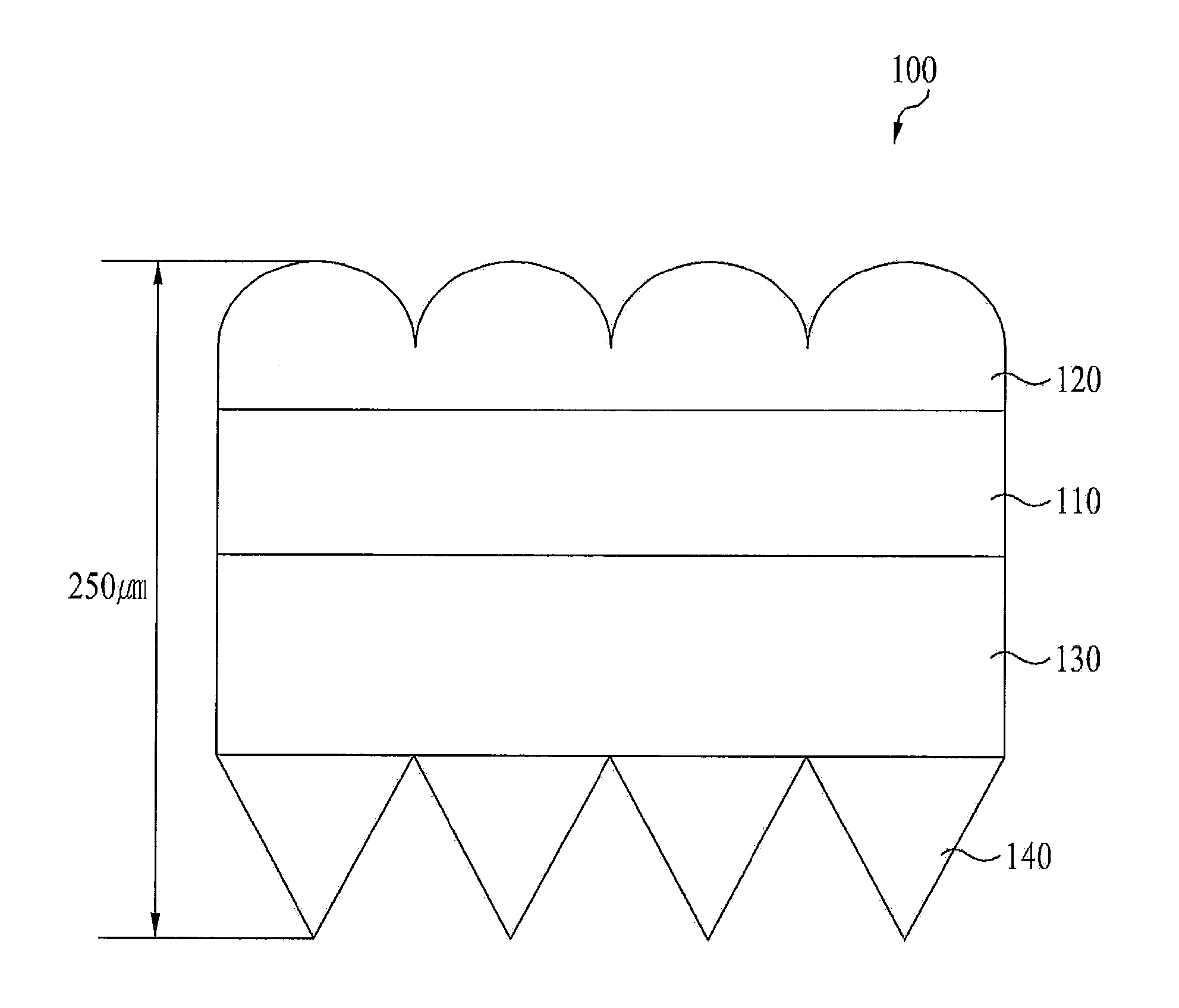
[0064]FIG. 6 is a sectional view illustrating a light guide plate according to one embodiment of the present invention.

[0065]As shown in FIG. 6, the light guide plate 100 according to one embodiment comprises a base film 110, a dot pattern 120 arranged on the base film 110, a base layer 130 arranged under the base film 110, and a prism pattern 140 arranged on the surface of the base layer 130.

[0066]The base film 110 is made of a transparent polyethylene terephthalate (PET). The base film 110 has a thickness of 75 to 250 μm, and may have a small thickness of about 50 μm, if possible. Other materials constituting the base film 110 may include polymethyl methacrylate (PMMA) and polycarbonate (PA). The total thickness of the light guide plate 100 depends on the thickness ...


PUM

PropertyMeasurementUnit
Thicknessaaaaaaaaaa
Thicknessaaaaaaaaaa
Transparencyaaaaaaaaaa

Abstract

Disclosed are a film-type light guide plate capable of readily securing mass-production and realizing low weight and slimness, a method for manufacturing the same and a backlight unit using the same. The method includes loading a base film on a movable first conveyor belt, coating a liquid ultraviolet curable resin on the first surface of the base film, rotating a surface-treated roll on the coated ultraviolet curable resin to form a prism pattern provided with a first protrusion pattern, and curing the prism pattern using an ultraviolet lamp.

Description

[0001]This application claims the benefit of Korean Patent Application No. 10-2008-0132143, filed on Dec. 23, 2008, which is hereby incorporated by reference as if fully set forth herein.BACKGROUND OF THE INVENTION[0002]1. Field of the Invention[0003]The present invention relates to a backlight unit. More specifically, the present invention relates to a film-type light guide plate capable of readily securing mass-production and realizing low weight and slimness, a method for manufacturing the same and a backlight unit using the same.[0004]2. Discussion of the Related Art[0005]Cathode ray tubes (CRTs) are general purpose display devices that are used for TVs, measurement instruments, and monitors such as information terminals. However, CRTs cannot actually meet demands for miniaturization and low weight due to their weight and size.[0006]Accordingly, counter to the recent trends toward miniaturization and low weight of electronic products, CRTs have limitations such as weight and siz...

Claims


Application Information

Patent Timeline
IPC IPC(8): F21V8/00B05D3/06
CPCB29D11/00663G02B6/0065G02B6/0043G02B6/0038G02B6/00B29D7/00G02B5/04
Inventor PARK, JAE-HYUN
Owner LG DISPLAY CO LTD
Why Eureka
Try Eureka