Shift device and method for securing shift device

A technology for equipment and shift shafts, which is applied to mechanical equipment, components with teeth, belts/chains/gears, etc., can solve the problems of cost fixation, anti-corrosion and anti-vibration measures, etc., to avoid corrosion and simplify The effect of mass production

Active Publication Date: 2018-06-08
SCHAEFFLER TECH AG & CO KG
View PDF12 Cites 0 Cited by
  • Summary
  • Abstract
  • Description
  • Claims
  • Application Information

AI Technical Summary

Problems solved by technology

However, this solution, which is inherently good and of simple construction, requires relatively complex fastening by means of shaft passages and pins
Anti-corrosion and anti-vibration measures can only be implemented with great effort using this solution

Method used


Image

  • Shift device and method for securing shift device
  • Shift device and method for securing shift device

Examples


Embodiment Construction

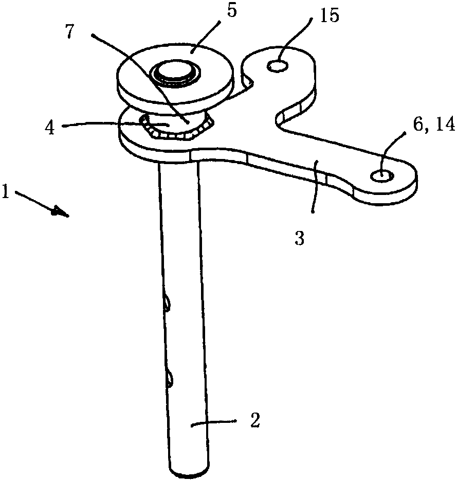
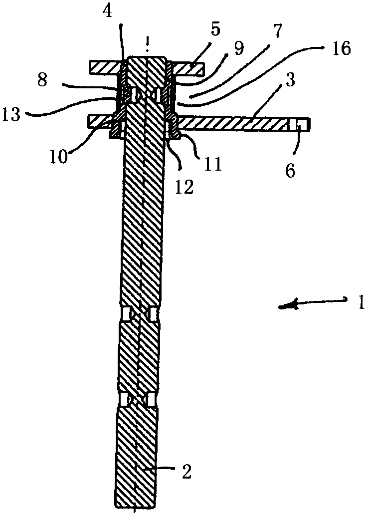
[0031] figure 1 The schematic diagram of FIG. 1 illustrates the design and function of a first variant of a shifting device 1 for a shift transmission or gearbox of a motor vehicle (not shown). The shifting device 1 has a shift shaft 2 of a transmission. The shifting shaft 2 is mounted rotatably and axially displaceably in a transmission housing, also not shown. The unit consisting of the selector lever 3 , the sleeve 4 or the disc 5 is fastened to the shift shaft 2 on the end side in a rotationally fixed manner. The selector lever 3 has at its free end a rod recess 6 for a ball head, on which a rod connection or a cable drive of a manual selector lever (not shown) can act in order to pivot The selector lever in turn rotates the selector shaft 2 by a defined rotational angle amount, which is necessary for changing gears.

[0032] The selector lever 6 has two arms arranged approximately perpendicular to each other. Angle α can also have an angle of 0°-360° depending on the in...


PUM


Abstract

The invention relates to a shift device (1) for a motor vehicle variable-speed gearbox, comprising a selector shaft (2) which can be rotated and axially displaced, a sleeve (4) which is secured to said selector shaft (2) at the end, a gear shift lever (3) that is rigidly secured to the sleeve and which can cause the selector shaft (2) to rotate, and a selector lever engagement (7) for a selector lever, which allows said selector shaft (2) to be axially displaced.

Description

technical field [0001] The invention relates to a shifting device for a motor vehicle gearbox, which has a shifting shaft, which is rotatable and axially displaceable, and a sleeve, which is on the end side affixed to the shift shaft; a selector lever fixedly connected to the sleeve and through which the selector shaft is rotatable; and a selector lever engagement mechanism for a selector lever through which the selector lever can Axially movable via the selector lever. Background technique [0002] In a motor vehicle with a manual transmission or a gearbox with automatic shifting, a shifting device, usually consisting of two levers, is required as an actuating device to move and turn the shifting shaft. One lever of this arrangement, usually the selector lever, pivots to move the shift shaft axially. Here, the selection movement on the selector lever is converted into a linear movement of the selector shaft. The other lever, usually the shift lever, turns the shift shaft...

Claims


Application Information

Patent Timeline
IPC IPC(8): F16H63/38
CPCF16H63/30F16H2063/3076F16H2063/3086
Inventor 约亨·勒费尔曼克劳斯·克拉默
Owner SCHAEFFLER TECH AG & CO KG
Why Eureka
Try Eureka