Gas-Liquid Separator and Refrigeration System With Gas-Liquid Seperator

a technology of gas-liquid separator and refrigeration system, which is applied in the direction of refrigerating machines, fluid circulation arrangement, lighting and heating apparatus, etc., can solve the problems of deteriorating performance, disturbing the liquid level, and the level of liquid refrigerant pool, so as to achieve enhanced gas-liquid separation performance

Inactive Publication Date: 2010-06-24
DAIKIN IND LTD
View PDF8 Cites 11 Cited by
  • Summary
  • Abstract
  • Description
  • Claims
  • Application Information

AI Technical Summary

Benefits of technology

[0036]According to the first aspect of the invention, since the inflow pipe (20) is provided with a fragmentation device (50), even if gas-liquid two-phase fluid flowing through the inflow pipe (20) forms a slug flow, large gas bubbles of gaseous fluid can be fragmentized to homogenize the gas-liquid two-phase fluid. As a result, the gas-liquid two-phase fluid can be introduced in a regular and stable flow condition into the vessel body (16).
[0037]On the other hand, in the interior of the vessel body (16), the gas-liquid two-phase fluid is separated into liquid fluid and gaseous fluid. Thus, a pool (23) of liquid fluid is formed in a lower side of the interior of the vessel body (16), while a pool (24) of gaseous fluid is formed in an upper side thereof. Since gas-liquid two-phase fluid is introduced in a regular flow condition into the vessel body (16), this reduces the disturbance of the liquid level of the pool (23) of liquid fluid, the spattering of the liquid fluid due to the disturbance and the mixing of gas bubbles into the pool (23) of liquid fluid. Thus, liquid fluid flowing from the pool (23) of liquid fluid to the liquid outflow pipe (30) can be prevented from mixing-in of gas refrigerant and gaseous fluid flowing from the pool (24) of gaseous fluid to the gas outflow pipe (40) can be prevented from mixing-in of liquid fluid. Therefore, the gas-liquid separation performance can be enhanced.
[0038]According to the second aspect of the invention, since the fragmentation device (50) comprises a mesh member (50), gas bubbles can surely be fragmentized and the resistance that gas-liquid two-phase fluid meets on the fragmentation device (50) can be relatively small. Thus, the gas-liquid two-phase fluid flowing into the vessel body (16) reaches a further regular and stable flow condition.
[0039]According to the third aspect of the invention, since the opening end (21) of the inflow pipe (20) and the opening end (41) of the gas outflow pipe (40) are placed to face each other in an upper part of the vessel body (16) and at opposite sides of the vessel body (16), gas-liquid two-phase fluid can be prevented from being directly introduced from the opening end (21) of the inflow pipe (20) to the pool (23) of liquid fluid in a lower part of the vessel body (16). In addition, gas-liquid two-phase fluid flowing through the opening end (21) of the inflow pipe (20) into the vessel body (16) can be prevented from hitting the inside wall of the vessel body (16) and thereby spattering. As a result, it can surely be prevented that gas bubbles are mixed into the pool (23) of liquid fluid and that the liquid level of the pool (23) gets disturbed.
[0040]Furthermore, since the opening end (41) of the gas outflow pipe (40) can be placed a certain distance away from the opening end (21) of the inflow pipe (20) in the vessel body (16), gas-liquid two-phase fluid flowing through the inflow pipe (20) into the vessel body (16) can be prevented from directly flowing out through the opening end (41) of the gas outflow pipe (40). Thus, liquid fluid flowing from the pool (23) of liquid fluid to the liquid outflow pipe (30) can surely be prevented from mixing-in of gaseous fluid and gaseous fluid flowing from the pool (24) of gaseous fluid to the gas outflow pipe can surely be prevented from mixing-in of liquid fluid.
[0041]According to the ninth aspect of the invention, since the opening end (21) of the inflow pipe (20) and the opening end (41) of the gas outflow pipe (40) are placed in an upper part of the vessel body (16) and arranged to face each other at longitudinally opposite sides of the vessel body (16), the distance between the opening end (21) of the inflow pipe (20) and the opposite part of the inside wall of the vessel body (16) can be long. Thus, gas-liquid two-phase fluid flowing through the inflow pipe (20) into the vessel body (16) can surely be prevented from hitting the inside wall of the vessel body (16) and thereby spattering. Therefore, the pool (23) of liquid fluid in a lower side of the interior of the vessel body (16) can be prevented from disturbance of its liquid level and mixing-in of gas bubbles. In addition, it can be prevented that fluid spattered by the hitting flows out through the gas outflow pipe (40).

Problems solved by technology

If such a slug flow is introduced through the inflow pipe (b) into the vessel body (a), a problem arises that the liquid level of the liquid refrigerant pool (e) is disturbed and the disturbance of the liquid level incurs spattering of the liquid refrigerant, resulting in mixing of the liquid refrigerant into gas refrigerant flowing out of the vessel body (a) and through the gas outflow pipe (d).
In addition, another problem arises that gas bubbles are mixed into the liquid refrigerant pool (e) and, therefore, gas refrigerant is mixed into liquid refrigerant flowing out of the vessel body (a) and through the liquid outflow pipe (c).
This causes a problem that spattered refrigerant directly flows out through the gas outflow pipe (d).
In addition, another problem arises that the spattered refrigerant falls into the liquid refrigerant pool (e), thereby disturbing the liquid level and mixing gas bubbles into the liquid refrigerant pool (e).
As seen from the above, the known gas-liquid separators have a problem that if gas-liquid two-phase refrigerant flowing through the inflow pipe forms a slug flow, they deteriorate its performance of separation of the gas-liquid two-phase refrigerant or deteriorate the reliability as a gas-liquid separator.
Furthermore, if the gas-liquid separator in a refrigeration system varies its refrigerant separation performance because of flow conditions of gas-liquid two-phase refrigerant, this causes variations in evaporation capacity of the evaporator and variations in condensation capacity of the condenser.
As a result, a problem arises that the refrigeration system cannot perform a stable operation.

Method used


Image

  • Gas-Liquid Separator and Refrigeration System With Gas-Liquid Seperator
  • Gas-Liquid Separator and Refrigeration System With Gas-Liquid Seperator
  • Gas-Liquid Separator and Refrigeration System With Gas-Liquid Seperator

Examples


embodiment 1

Effects of Embodiment 1

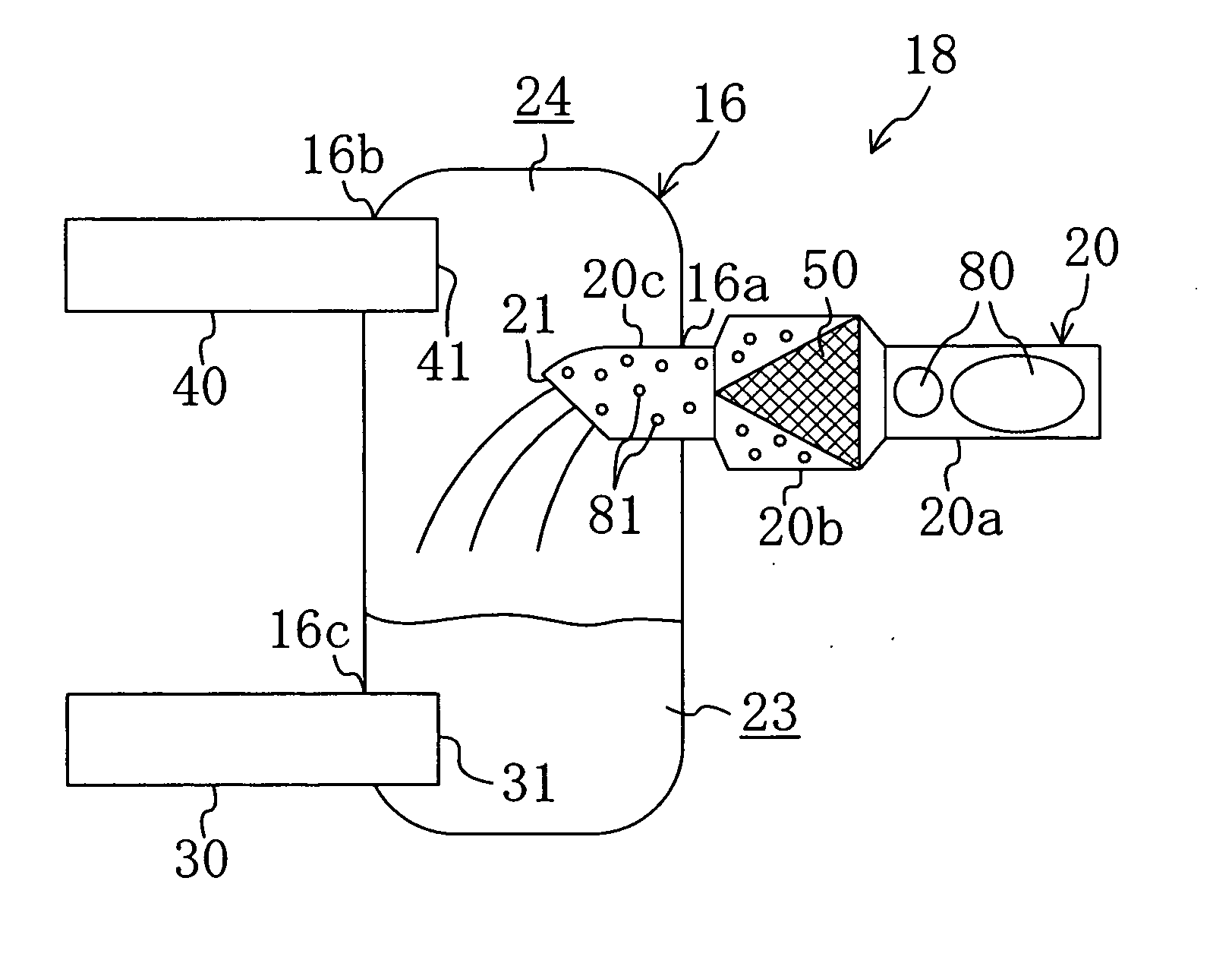
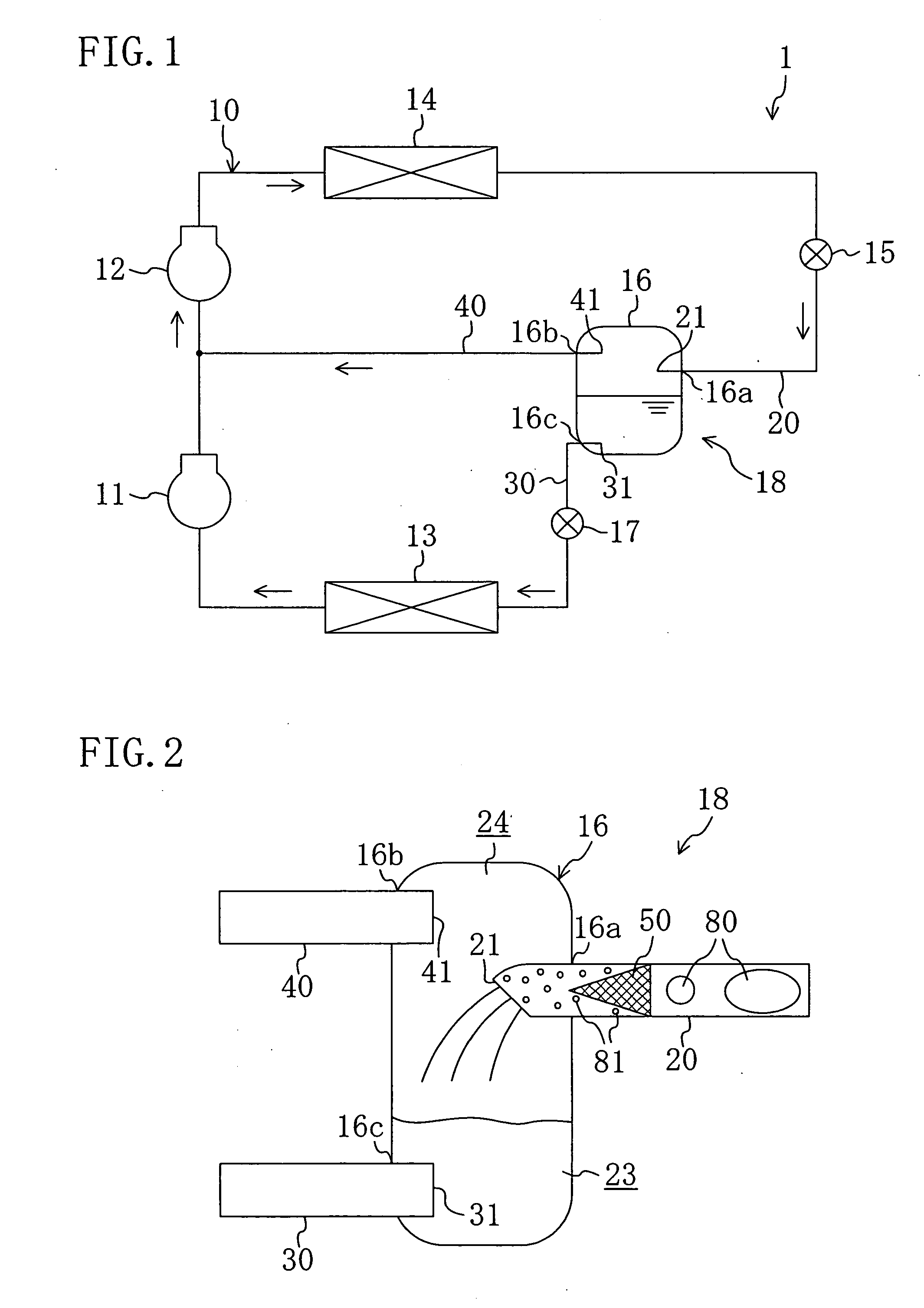
[0100]Since, in the refrigeration system (1), a mesh member (50) is placed in the inflow pipe (20) of the gas-liquid separator (18), gas bubbles (80) of gas refrigerant in gas-liquid two-phase refrigerant flowing through the inflow pipe (20) can surely be fragmentized, whereby the gas-liquid two-phase refrigerant can be homogenized. Thus, the gas-liquid two-phase refrigerant is introduced in a regular and stable flow condition into the vessel body (16). This reduces the disturbance of the liquid level of the pool (23) of liquid refrigerant, the spattering of liquid refrigerant due to the liquid level disturbance, and the mixing of gas bubbles into liquid refrigerant, such as due to bubbling of the pool (23) of liquid refrigerant.

[0101]Furthermore, since the inflow pipe (20) is disposed to horizontally extend over the length thereof, large bubble masses of gas refrigerant in the gas-liquid two-phase fluid are likely to be broken, which restrains the production ...

modification 1

of Embodiment 2

[0129]This embodiment is configured, as shown in FIG. 6, by placing a mesh member (50) in the inflow pipe (20) of the gas-liquid separator (18) according to Embodiment 2.

[0130]According to this embodiment, since the mesh member (50) is placed in the inflow pipe (20), gas-liquid two-phase refrigerant introduced through the inflow pipe (20) into the vessel body (50) is homogenized, whereby the flow condition of the gas-liquid two-phase refrigerant becomes regular and stable. This prevents disturbance of the liquid level of the pool (23) of liquid refrigerant, spattering of liquid refrigerant into the pool (24) of gas refrigerant due to the liquid level disturbance, and mixing of gas bubbles into liquid refrigerant, such as due to bubbling of the pool (23) of liquid refrigerant. Thus, the gas-liquid separation performance of the gas-liquid separator (18) can be further enhanced.

[0131]The rests of the configuration and operational behavior and the other effects are the sa...

modification 2

of Embodiment 2

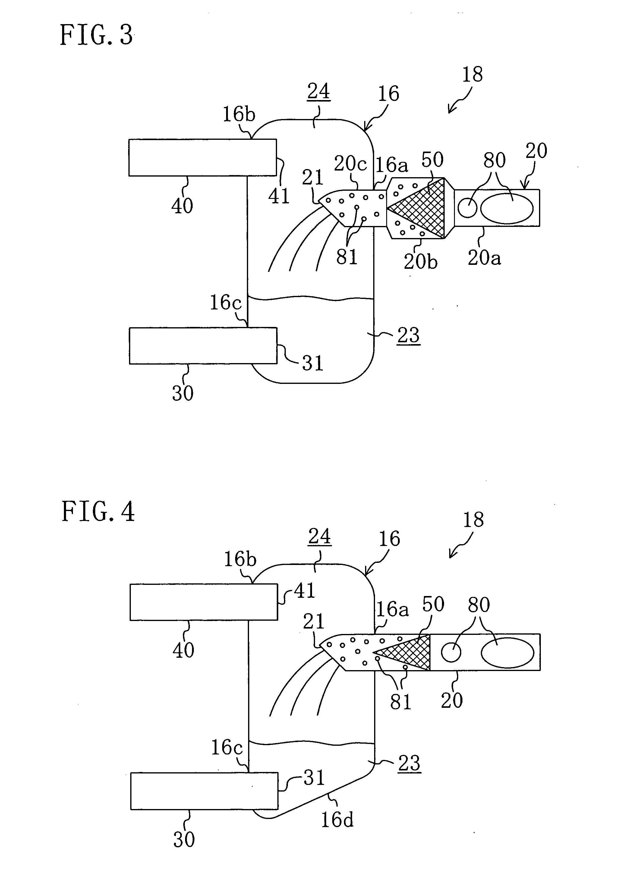
[0132]This embodiment is configured, as shown in FIG. 7, by installing the vessel body (16) of the gas-liquid separator (18) according to Embodiment 2 to incline it downward from its one end surface through which the gas outflow pipe (40) passes towards its other end surface through which the liquid outflow pipe (30) passes. Thus, an under part (16d) of the peripheral surface of the cylindrical vessel body (16) inclines downward towards a point thereof corresponding to the opening end (31) of the liquid outflow pipe (30) and is thereby constituted as the under surface of the vessel body (16). Furthermore, in this embodiment, only the vessel body (16) is placed at an angle but the pipes (20, 30, 40) are horizontally placed in and around the vessel body (16).

[0133]According to this embodiment, the vessel body (16) can surely have a pool of liquid refrigerant around the opening end (31) of the liquid outflow pipe (30) even if the amount of liquid refrigerant therein is s...


PUM


Abstract

A refrigeration system includes a refrigerant circuit including a gas-liquid separator (18) and operating in a two-stage compression and two-stage expansion refrigeration cycle. In the refrigerant circuit, intermediate-pressure gas-liquid two-phase refrigerant having flowed through an intermediate expansion valve after flowing through an outdoor heat exchanger is introduced through an inflow pipe (20) of the gas-liquid separator (18) into the vessel body (16) thereof and separated therein into liquid refrigerant and gas refrigerant. The liquid refrigerant flows out through a liquid outflow pipe (30), then flows through a main expansion valve and then through a refrigeration heat exchanger and is then sucked into a low-pressure stage compressor. The gas refrigerant flows out through a gas outflow pipe (40), is then fed to the suction side of a high-pressure stage compressor and is then sucked into the high-pressure stage compressor together with refrigerant discharged from the low-pressure stage compressor. The inflow pipe (20) is provided with a mesh member (50) for fragmentizing gas bubbles (80) of gas refrigerant in the gas-liquid two-phase refrigerant.

Description

TECHNICAL FIELD[0001]This invention relates to gas-liquid separators for separating gas-liquid two-phase fluid into liquid fluid and gaseous fluid and refrigeration systems including a refrigerant circuit with such a gas-liquid separator.BACKGROUND ART[0002]Conventional refrigeration systems include those including a refrigerant circuit operating in a two-stage compression and two-stage expansion refrigeration cycle. Furthermore, among such refrigeration systems include those including a gas-liquid separator for separating gas-liquid two-phase fluid into liquid fluid and gaseous fluid (see, for example, Patent Document 1).[0003]The refrigeration system disclosed in the above Patent Document 1 is an air conditioning system including a refrigerant circuit operating in a two-stage compression and two-stage expansion refrigeration cycle during a heating operation. The refrigerant circuit is provided with a gas-liquid separator for separating gas-liquid two-phase refrigerant into gas ref...

Claims


Application Information

Patent Timeline
Patent Type & Authority Applications(United States)
IPC IPC(8): F25B1/00F25B43/00
CPCF25B1/10F25B41/00F25B2400/23F25B2400/13F25B43/00
Inventor FUJIMOTO, SHUUJIYAMAGUCHI, TAKAHIRO
Owner DAIKIN IND LTD
Why Eureka
Try Eureka