
Encoding and modulating method, and decoding method for wireless communication apparatus

a wireless communication and modulation technology, applied in the field of encoding and modulation methods, decoding methods for wireless communication apparatus, can solve problems such as ineffective bi-id techniques, and achieve the effects of reducing the loss of transmission speed, reducing processing quantity to be treated by a decoder, and minimizing extended mapping

Inactive Publication Date: 2010-06-10
KOKUSA ELECTRIC CO LTD
View PDF16 Cites 22 Cited by
  • Summary
  • Abstract
  • Description
  • Claims
  • Application Information

AI Technical Summary

Benefits of technology

[0012]The EXIT charts shown in FIG. 31 and FIG. 33 demonstrate that the EXIT curve concerning the demodulator and the EXIT curve concerning the decoder are separated from each other except at an intersection. An area defined between the EXIT curve concerning the demodulator and the EXIT curve concerning the decoder is known to indicate a loss in a transfer rate. When the area approaches to 0, it means that the transfer rate approaches to the Shannon limit while being restricted by a constellation of a modulated signal. This is interpreted as described below. Namely, when the EXIT curve concerning the demodulator and the EXIT curve concerning the decoder are separated from each other, it means that: information inputted from the demodulator (decoder) to the decoder (demodulator) contains a large amount of redundant information; and the pieces of mutual information are largely improved. In other words, the transfer rate decreases. From this viewpoint, a BICM-ID technique suffering a small loss in the transfer rate is preferred to the BICM-ID techniques described in “Optimized Symbol Mappings for Bit-Interleaved Coded Modulation with Iterative Decoding” by F. Schereckenbach, N. Gortz, J. Hagenauer, and G. Bauch (IEEE GLOBECOM 2003, pp. 3316-3320, 2003) and “Extended Mappings for Bit-Interleaved Coded Modulation” by P. Henkel (IEEE PIMRC, 2006). Therefore, the first object of the present invention is to provide the BICM-ID technique suffering a small loss in the transfer rate.
[0013]The BICM-ID technique described in “Design of Low-Density Parity-Check Codes for Modulation and Detection” by S. ten Brink, G. Kramer, and A. Ashikhmin (IEEE Transactions on Communications, Vol. 52, No. 4, April 2004) succeeds the specialty of the LDPC code. The EXIT chart is used to signify that the BICM-ID technique suffers a very small loss in a transfer rate. However, since the BICM-ID technique employs the LDPC code that is a powerful code, it has such a drawback that a processing quantity to be treated by a decoder increases. Accordingly, the second object of the present invention is to provide a BICM-ID technique allowing the decoder to treat a small processing quantity.
[0016]If EXIT curves concerning a decoding technique and a demodulation technique are well-matched each other, a loss in a transmission speed is decreased. Accordingly, transmission can be achieved with the Shannon limit attained.
[0017]According to another aspect of the invention, since the iterative code is used as a basic code for encoding, a processing quantity to be treated by a decoder can be reduced.

Problems solved by technology

This means that the BICM-ID technique is ineffective.

Method used


Image

  • Encoding and modulating method, and decoding method for wireless communication apparatus
  • Encoding and modulating method, and decoding method for wireless communication apparatus
  • Encoding and modulating method, and decoding method for wireless communication apparatus

Examples


first embodiment

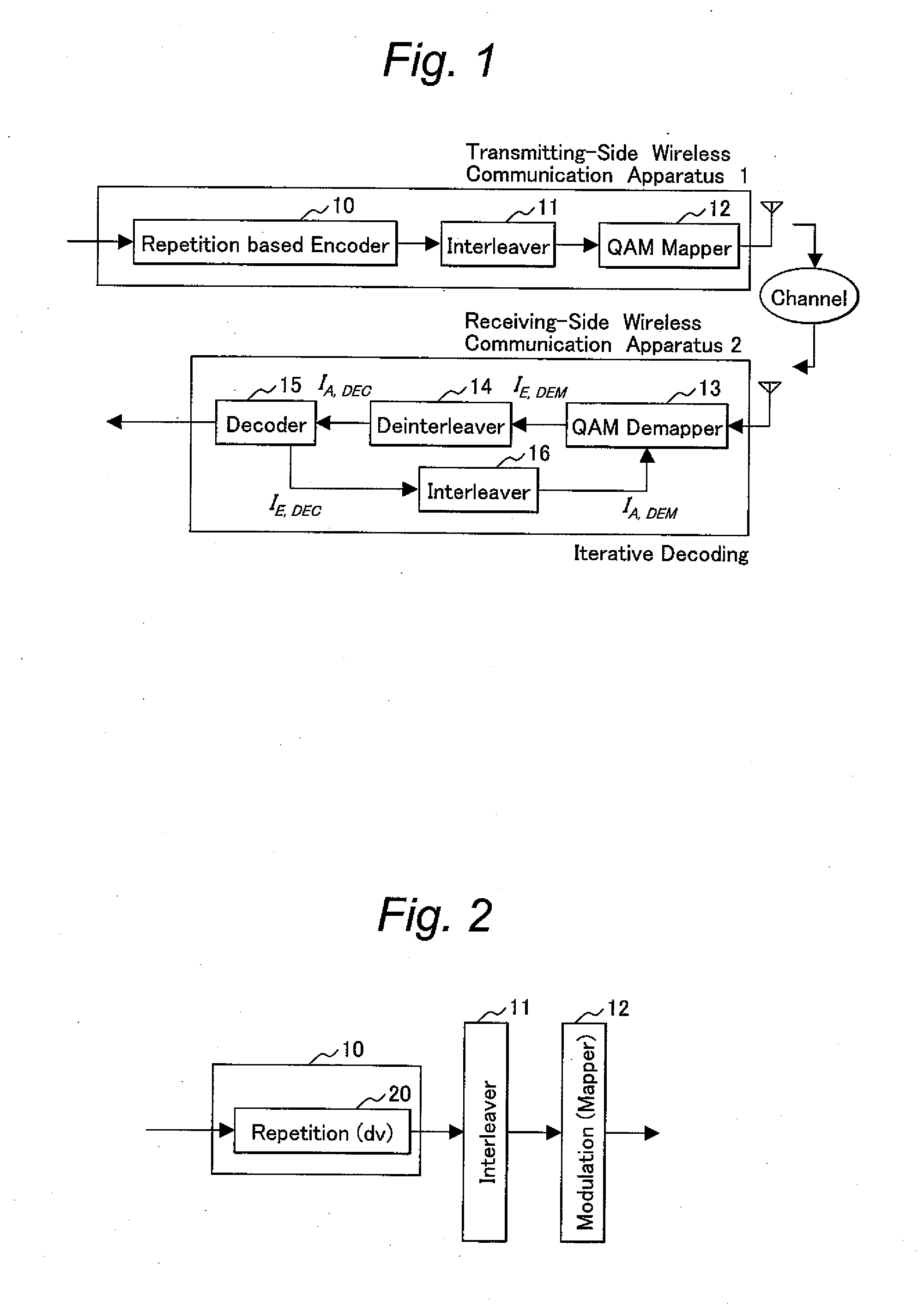
[0053]FIG. 2 shows the configuration of transmitting-side wireless communication apparatus in accordance with the first embodiment. The encoder 10 includes a bit duplicator 20 that performs simple iterative processing alone. Inputted information bits are duplicated into dv bits, and transmitted via the interleaver 11 and modulator 12.

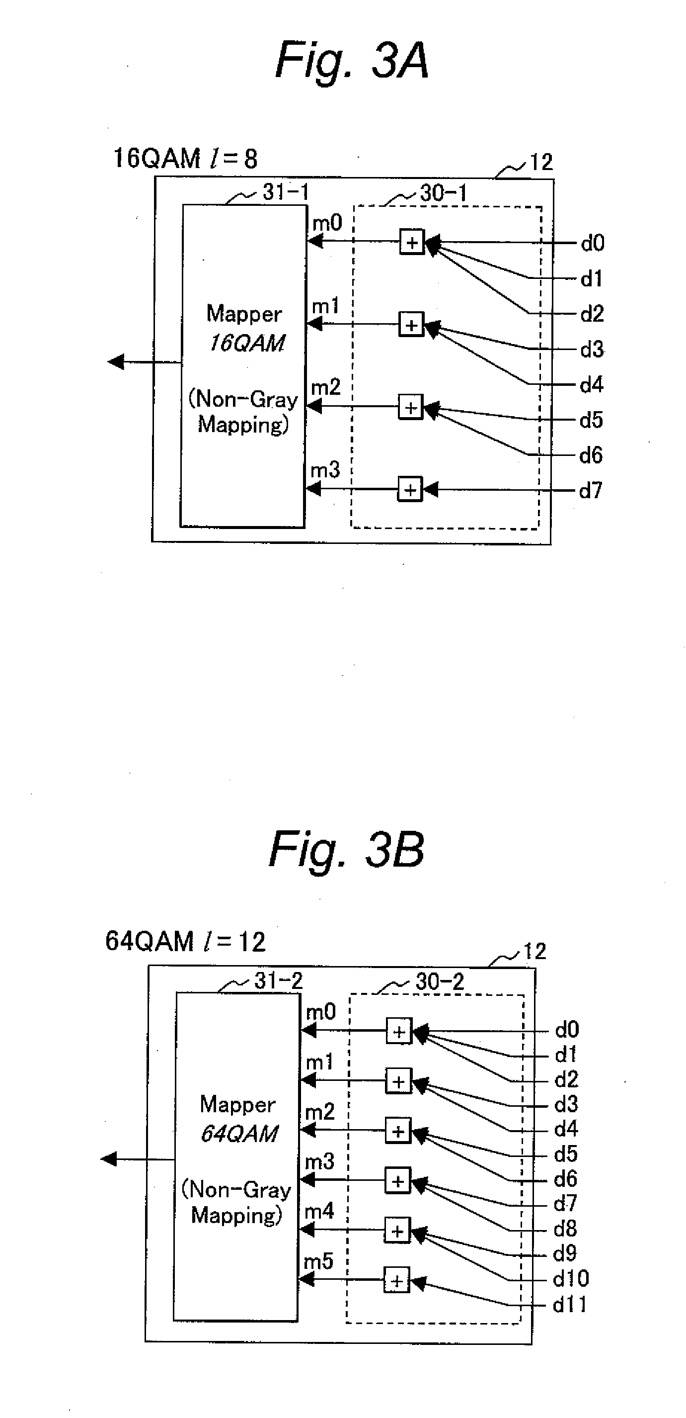
[0054]FIG. 3A to FIG. 3C show examples of the configuration of the modulator (mapper) 12. The modulator 12 shown in FIG. 3A to FIG. 3C is an example of a modulator that performs extended mapping. FIG. 3A shows an example in which an 8-bit code word is mapped into a symbol representing any of sixteen constellations (16 QAM (1=8)). FIG. 3B shows an example in which a 12-bit code word is mapped into a symbol representing any of sixty-four constellations (64 QAM (1=12)). FIG. 3C shows an example in which a 16-bit code word is mapped into a symbol representing any of 256 constellations (256 QAM (1=16)). In the examples, the modulator 12 includes a bit thinni...

second embodiment

[0079]Next, a second embodiment will be described below. In the second embodiment, an iterative code is used for encoding. However, in the first embodiment, all information bits are encoded iteratively dv times. In contrast, as shown in FIG. 14, bit duplicators 20-1 to 20-n for which different numbers of times of iteration are designated are used at a predetermined ratio (a_1, a_2, etc., and a_n). EXIT curves concerning iterative codes specifying the different number of times of iteration have different shapes. The larger the number of times of iteration is, the downward convexity becomes outstanding. Therefore, when the multiple numbers of times of iteration are used in combination, the freedom in determining the shape of the EXIT curve is expanded. The EXIT curve that well matches a modulation technique can be realized. Decoding processing employed in the second embodiment is, as shown in FIG. 15, nearly identical to that shown in FIG. 7 and employed in the first embodiment. A dif...

third embodiment

[0080]Next, a third embodiment will be described below. In the third embodiment, a parity bit is added prior to encoding to be performed according to an iterative code. As shown in FIG. 16, in the encoder 10, a parity appending block 1600 that produces a parity bit from (dc−1) information bits and outputs dc bits which include information bits is disposed in a stage preceding the bit duplicator 20 that performs iterative encoding. The parity appending block 1600 includes serial-parallel converters (21 and 23) for bits and an exclusive OR gate 22. Decoding processing employed in the third embodiment is, as shown in FIG. 17, achieved by connecting a check-node decoder, which computes a parity bit, to a variable-node decoder. As a decoding procedure, pieces of processing shown in any of FIG. 18A to FIG. 18C are substituted for those shown in FIG. 11.

[0081]In FIG. 18A, pieces of a priori information 1800 fed from the deinterleaver 14 are subjected to the computation expressed by the equ...


PUM


Abstract

Provided is a bit interleaved coded modulation-iterative decoding (BICM-ID) technique suffering a small loss in a transfer rate. A BICM-ID technique allowing a decoder to treat a small processing quantity is also provided. Encoding is carried out according to a code based on an iterative code. Encoded bits are reordered during interleaving processing, subjected to multi-valued modulation through extended mapping, and then transmitted. The extended mapping includes number-of-bits thinning processing of thinning l bits into m bits (m<l), and non-gray mapping. During the number-of-bits thinning processing, at least one of a predetermined number of bits is determined with only one of interleaved bits.

Description

CLAIM OF PRIORITY[0001]The present application claims priority from Japanese Patent Application JP2008-303429 filed on Nov. 28, 2008, the content of which is hereby incorporated by reference into this application.BACKGROUND OF THE INVENTION[0002]1. Field of the Invention[0003]The present invention relates to an encoding and modulating method for wireless communication apparatus that transmits or receives data through a wireless propagation channel, and a decoding method for the wireless communication apparatus.[0004]2. Description of the Related Art[0005]For years, a commitment to a subject of how to realize efficient communications while attaining the Shannon limit, which is the theoretical limit of information through a channel, by appropriately combining an encoding technique and a modulation technique as a wireless communication technique for mobile communications or the like has been made in earnest. Therefore, a specialized encoding (error-correction encoding) technique has be...

Claims


Application Information

Patent Timeline
Patent Type & Authority Applications(United States)
IPC IPC(8): H03M13/05G06F11/10
CPCH03M13/255H04L1/0057H04L1/0071H04L27/3433H04L27/02H04L27/34H04L1/08
Inventor YANO, TAKASHIMATSUMOTO, TADASHI
Owner KOKUSA ELECTRIC CO LTD
Learn More