
Worm gear for electric assisted steering apparatus and method controlling the movement of the worm shaft in a worm gearing

Inactive Publication Date: 2010-06-10
TRW LIMITED
View PDF3 Cites 32 Cited by
  • Summary
  • Abstract
  • Description
  • Claims
  • Application Information

AI Technical Summary

Benefits of technology

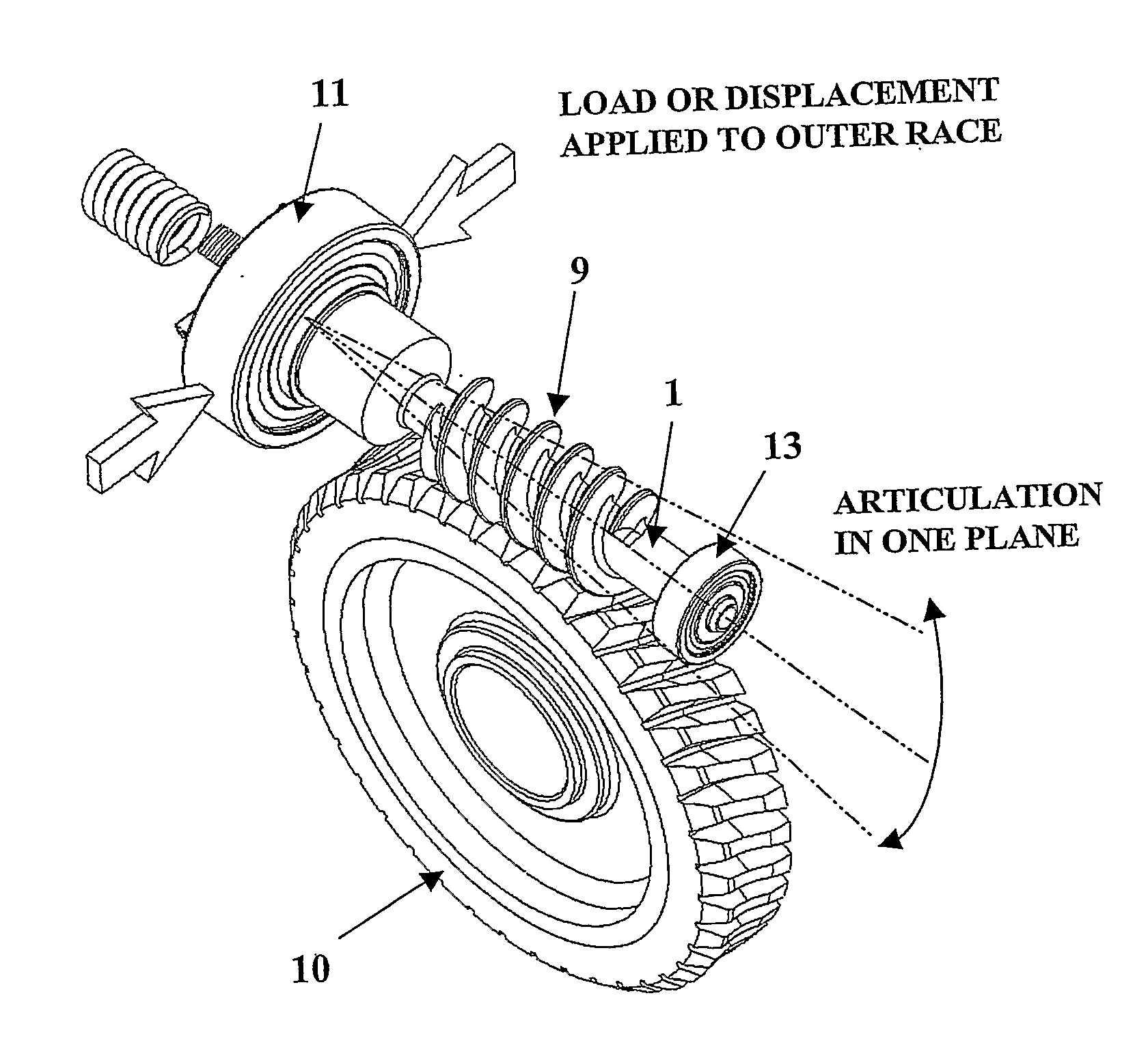
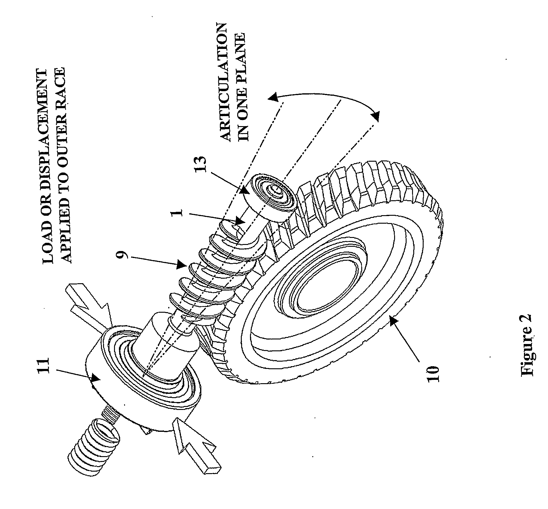
[0008]By providing differing degrees of radial freedom through use of a non-round outer bearing race groove it has been found to be possible to permit a relatively large angular movement of the worm shaft predominantly in one desired plane whilst restricting the angular movement in the plane orthogonal to the desired plane whilst restricting the amount of axial movement of the worm shaft. For a worm and wheel gearbox in an electric power assisted steering system the desired plane is usually that which passes through both the axis of the worm shaft and intersects the teeth of the gear wheel halfway across their width. This combination is good for reducing unwanted noise.
[0012]The bearing may include an outer race which is flexible and which is generally circular prior to use and is distorted when in use by applying forces to it. The inner race should preferably be as circular as possible to avoid unwanted changes in the distribution of ball clearances as the inner race rotates.
[0028]In another alternative, the bearing could be manufactured such that the ball groove in the outer race is non-round thus avoiding the requirement to distort it after installation in the gearbox housing. This requires the correct orientation of the outer race in the gearbox housing to ensure that the freedom to pivot is in the correct plane.

Problems solved by technology

There exists, however, a problem in such gearboxes with noise and vibration due to incorrect meshing between the worm and wheel.
A worm and wheel gearbox, for an electric power steering system, having a fixed centre distance between the axes of the worm and gear wheel is prone to rattle when transmitting zero or low torque if there is excessive clearance between the gear teeth of the worm and those of the gear wheel.
Alternatively, it is prone to having high friction if there is forced meshing between the worm and wheel due to interference between the teeth.

Method used


Image

  • Worm gear for electric assisted steering apparatus and method controlling the movement of the worm shaft in a worm gearing
  • Worm gear for electric assisted steering apparatus and method controlling the movement of the worm shaft in a worm gearing
  • Worm gear for electric assisted steering apparatus and method controlling the movement of the worm shaft in a worm gearing

Examples


Embodiment Construction

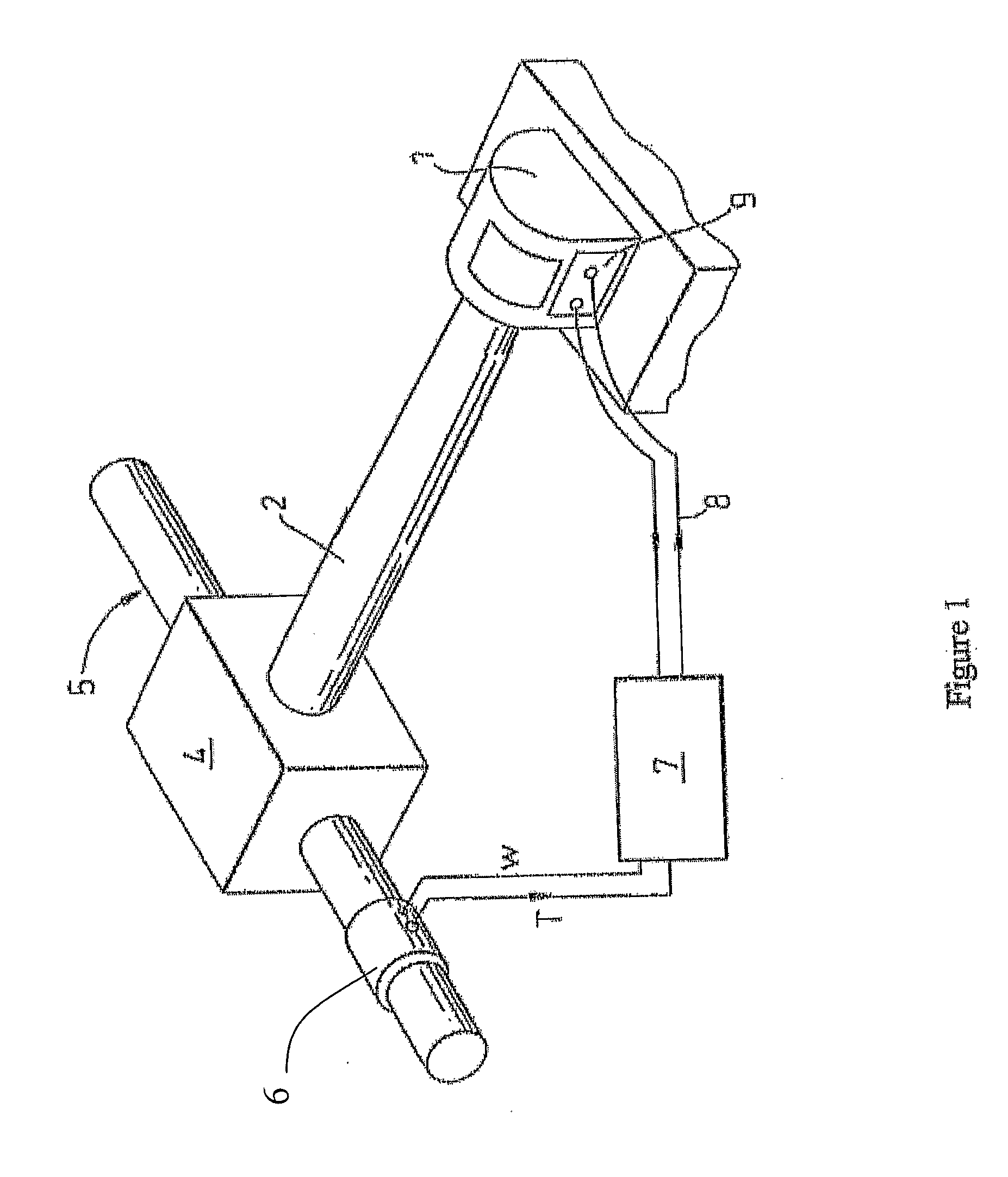
[0077]A steering apparatus for a vehicle is shown in FIG. 1 of the accompanying drawings. The apparatus comprises an electric motor 1 which acts upon an output shaft 2 through an optional clutch 3 to a gearbox 4 of the worm and wheel type. The steering column carries a torque sensor 6 that is adapted to measure the torque carried by the steering column 5. This torque is produced by the driver turning the steering wheel. The output signal T from this sensor is fed to a signal processing means in the form of a digital signal processor 7. The signal processor generates a motor drive signal indicative of the torque required from the motor, and this signal is applied to a motor drive circuit 9 through wires 8.

[0078]The gearbox 4 is shown in more detail in FIGS. 2 and 3 of the accompanying drawings. The input shaft 1 is connected to the output of the motor, and carries a worm gear 9, and an output shaft carries a wheel gear 10. The teeth of the worm and wheel intermesh to transfer the tor...


PUM


Abstract

An electric power assisted steering system comprises a motor connected to a portion of a steering mechanism through a worm carried by a worm shaft and a wheel carried by an output shaft operatively coupled to the steering mechanism. The shaft is supported in at least one bearing which has some internal clearances and supports the worm shaft in such a manner that it is free to pivot through an angle in planes which include its own axis due to a degree of axial free play of the first bearing assembly. The bearing assembly comprises an inner race having a groove, an outer race having a groove, and a plurality of ball bearings located between the inner and outer races, and in which the outer race groove is not round when in its position of use such that the ball bearings permit a greater freedom of movement of the inner race relative to the outer race in a first radial direction than in a second radial direction that is orthogonal to the first direction. Tensile or compressive forces may be applied to the bearing assembly to cause the part of the assembly to become not round.

Description

CROSS REFERENCE TO RELATED APPLICATIONS[0001]This application is a National Stage of International Application No. PCT / GB2007 / 004183 filed Nov. 2, 2007, the disclosures of which are incorporated herein by reference in entirety, and which claimed priority to Great Britain Patent Application No. 0621985.1 filed Nov. 4, 2006, and Great Britain Patent Application No. 0625359.5 filed Dec. 20, 2006 the disclosures of which are incorporated herein by reference in entirety.BACKGROUND OF THE INVENTION[0002]This invention relates to improvements in electric power assisted steering apparatus and in particular to gearbox assemblies for use in electric power assisted steering systems of the kind which incorporate a worm and wheel gear assembly for transferring torque from an electric motor to a steering shaft or output shaft operatively connected thereto.[0003]It is known to provide a power steering system for a vehicle comprising an electric motor having a stator and a rotor, an input shaft ope...

Claims


Application Information

Patent Timeline
IPC IPC(8): B62D5/04F16H55/18
CPCF16H2057/0222F16C2380/27F16C23/06F16H1/16F16C33/58F16H2057/0213Y10T74/19623B62D5/0409F16C2326/24F16C2361/61
Inventor WILKES, MARK ANTHONYAPPLEYARD, MICHAEL
Owner TRW LIMITED
Learn More