
Relay device, relay method, and program

a relay method and relay technology, applied in the field of relay devices and relay methods, can solve problems such as packet loss, packet congestion, packet congestion, etc., and achieve the effect of suppressing packet congestion

Inactive Publication Date: 2010-05-27
SONY CORP
View PDF9 Cites 37 Cited by
  • Summary
  • Abstract
  • Description
  • Claims
  • Application Information

AI Technical Summary

Benefits of technology

[0015]According to an aspect of the present invention, in accordance with the reception band of a stream of received packets, transmission of multicast packets is controlled. In particular, according to an aspect of the present invention, the occurrence of congestion of packets is suppressed.

Problems solved by technology

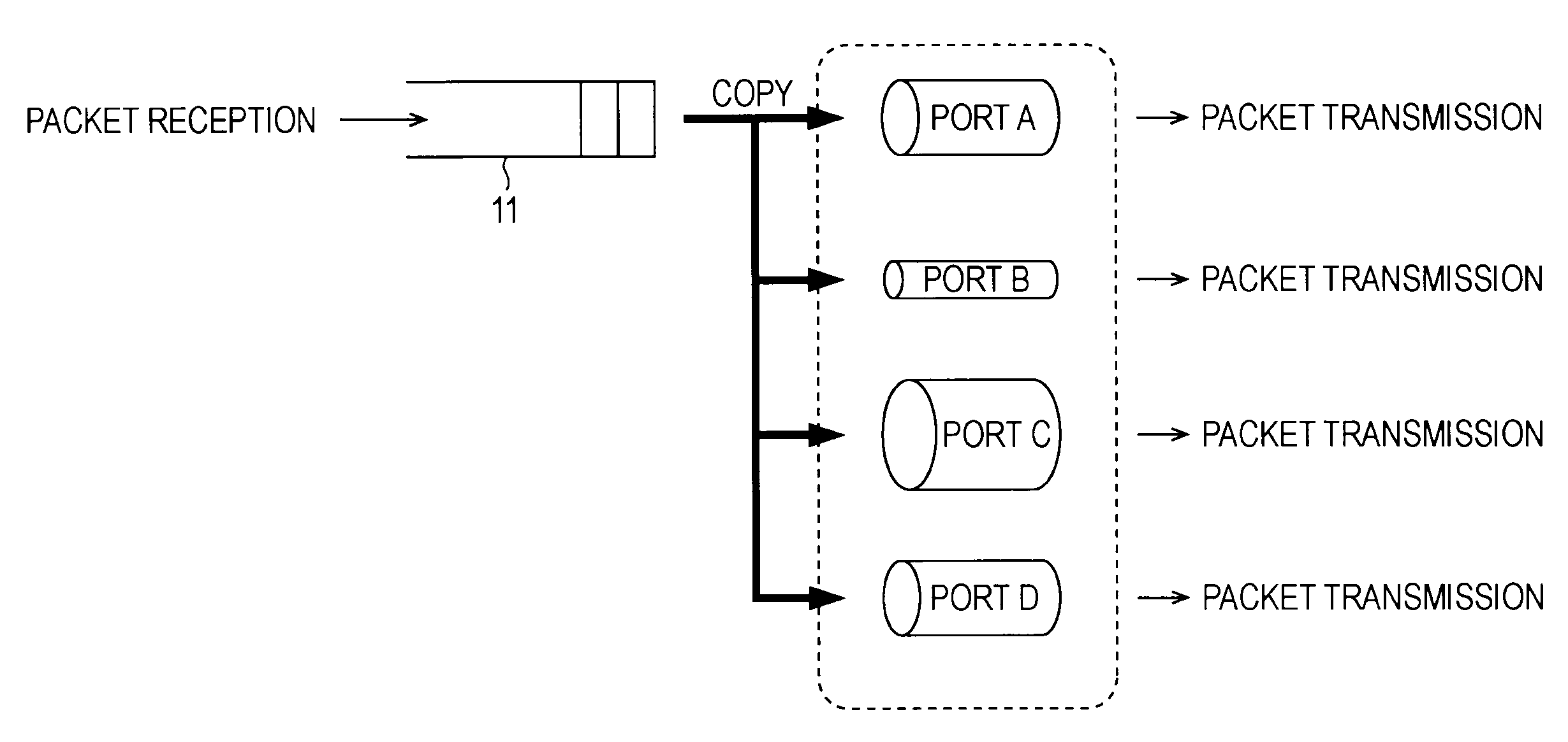
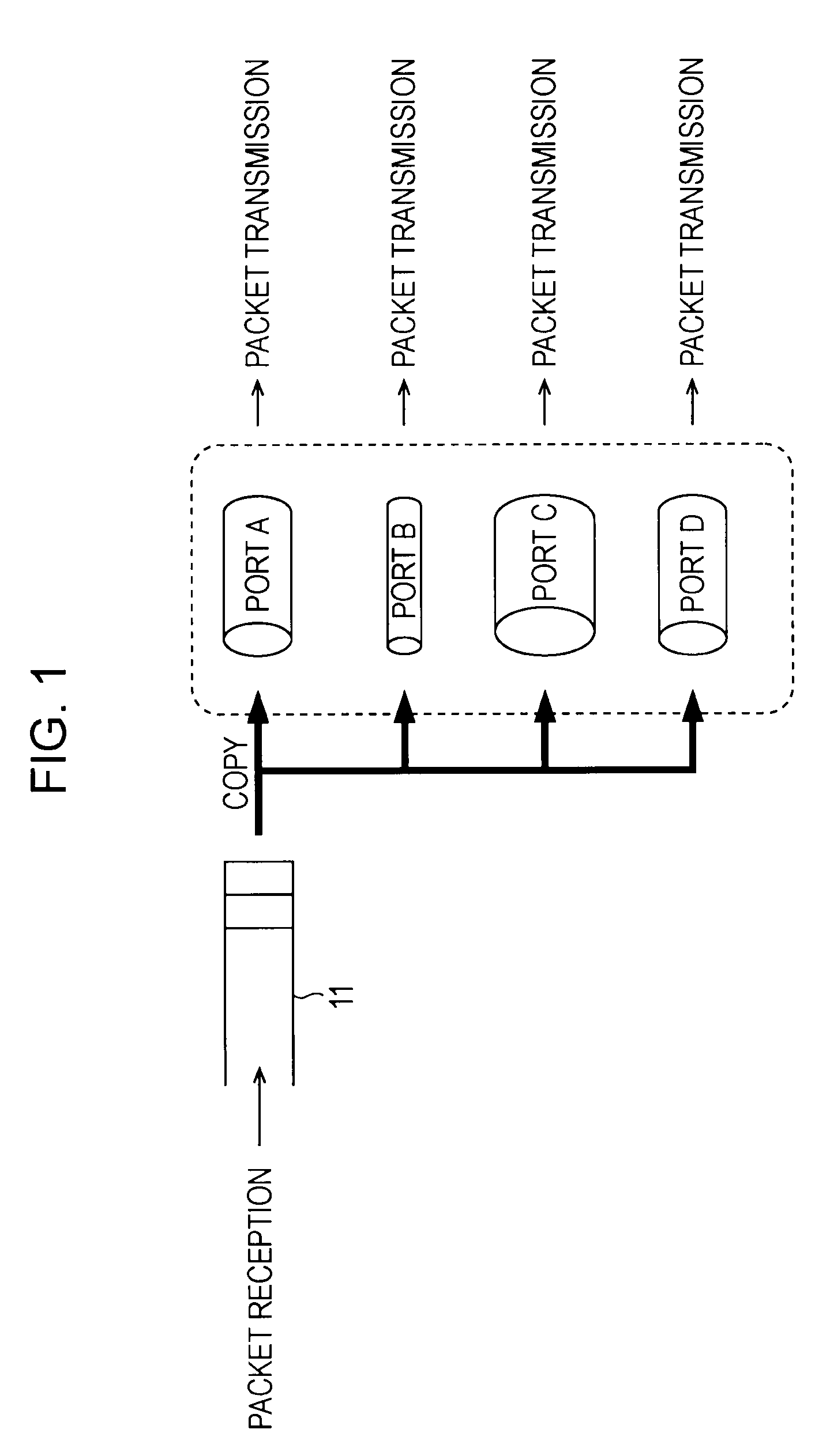
However, many of existing standard Layer 2 switches (switching hubs) used in home networks, which are Layer 2 (L2, Data Link Layer) networks, do not sufficiently comply with multicast specifications, whereby multicast packets are processed similarly to broadcast packets.
Thus, for example, in a case where the port B is connected to a network having a lower transfer speed than networks connected to the other ports, the port B becomes a bottleneck when a multicast packet is transmitted, whereby congestion of packets, packet loss, and the like may occur within the Layer 2 switch.

Method used


Image

  • Relay device, relay method, and program
  • Relay device, relay method, and program
  • Relay device, relay method, and program

Examples


Embodiment Construction

[0023]In the following, embodiments to which the present invention is applied will be described with reference to the drawings.

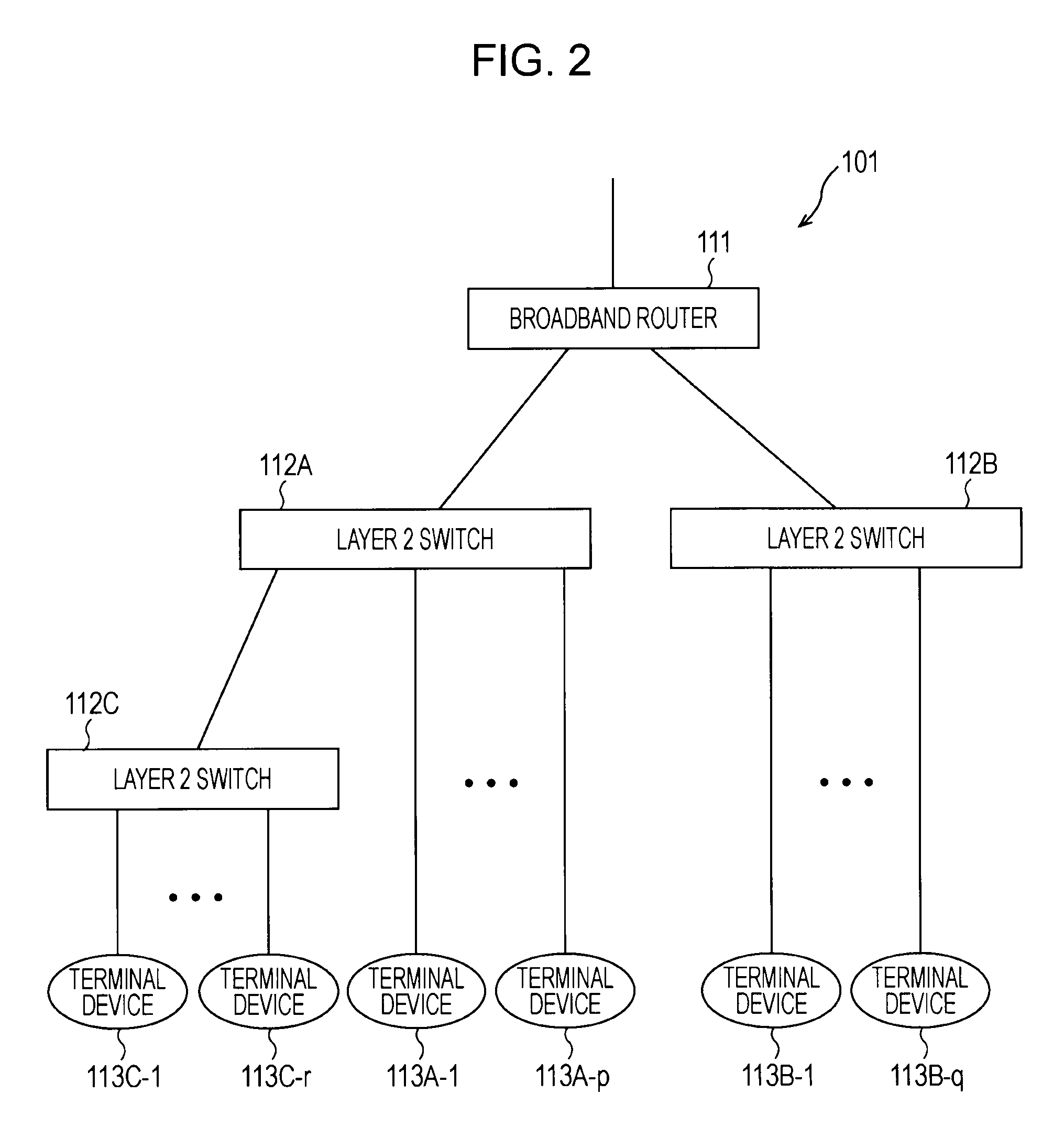
[0024]FIG. 2 is a block diagram showing an embodiment of a network system to which the present invention is applied. A network system 101 in FIG. 2 is, for example, a general home network system. The network system 101 includes a broadband router 111 that performs connection to an external network such as the Internet or a carrier network (for example, a CDN (Content Delivery Network) or the like) and that relays packets on the basis of at least Layer 2 and layer 3 (L3, Network Layer) protocols, Layer 2 switches 112A through 112C that are relay devices for relaying packets on the basis of at least a Layer 2 protocol, and terminal devices 113A-1 through 113A-p, 113B-1 through 113B-q, and 113C-1 through 113C-r that are network-ready devices such as information processing devices, AV (Audio / Visual) devices, and home electric appliances. The network system 101 c...


PUM


Abstract

A relay device, a relay method, and a program that can suppress occurrence of congestion of packets, for example applied to a Layer 2 switch. In a case a reception control unit receives multicast packets through ports, the reception control unit stores the received multicast packets in a buffer. A reception-band measurement unit measures the reception band of a stream of multicast packets passing through a channel from the reception control unit to the buffer in unit time and sends a notification of a measured value to a transmission control unit every unit time. The transmission control unit performs control so as not to transmit the multicast packets stored in the buffer from a port or ports whose transmission band is lower than a transmission threshold value corresponding to the reception band.

Description

TECHNICAL FIELD[0001]The present invention relates to a relay device, a relay method, and a program. The present invention relates more particularly to a relay device, a relay method, and a program that suppress congestion of packets.BACKGROUND ART[0002]These days, backbones of IP (Internet Protocol) networks have been complying with multicast-packet specifications, whereby multicast packets are delivered through home networks. In particular, in a service such as IPTV (Internet Protocol TV), multicast packets may be delivered through home networks at 20 Mbps (Bits Per Second) or higher.[0003]However, many of existing standard Layer 2 switches (switching hubs) used in home networks, which are Layer 2 (L2, Data Link Layer) networks, do not sufficiently comply with multicast specifications, whereby multicast packets are processed similarly to broadcast packets.[0004]For example, in an existing standard Layer 2 switch that does not sufficiently comply with multicast specifications, as s...

Claims


Application Information

Patent Timeline
IPC IPC(8): H04L12/26H04L12/28H04L47/80
CPCH04L12/1877H04L12/1886H04L49/201H04L47/11H04L47/10
Inventor SHIGEI, HIROYUKI
Owner SONY CORP
Learn More