
Constant pressure infusion process for resin transfer molding

a technology of resin transfer molding and infusion process, which is applied in the direction of transportation and packaging, butter manufacturing, other domestic articles, etc., can solve the problems of reducing the overall strength and quality of the composite so manufactured, reducing the cost of fabricating prepregs, and each of these processes may be problematic, so as to increase the strength and quality of the composite. , the effect of low porosity and high fiber volume fraction

Active Publication Date: 2010-05-20
CYTEC TECH CORP
View PDF4 Cites 38 Cited by
  • Summary
  • Abstract
  • Description
  • Claims
  • Application Information

AI Technical Summary

Benefits of technology

"The patent text is about the need for composites with high fiber volume fractions and low porosity, which will make them stronger and better quality. The text also describes methods and apparatus for processing these materials, which will reduce the cost of production."

Problems solved by technology

Each of these processes may be problematic, however.
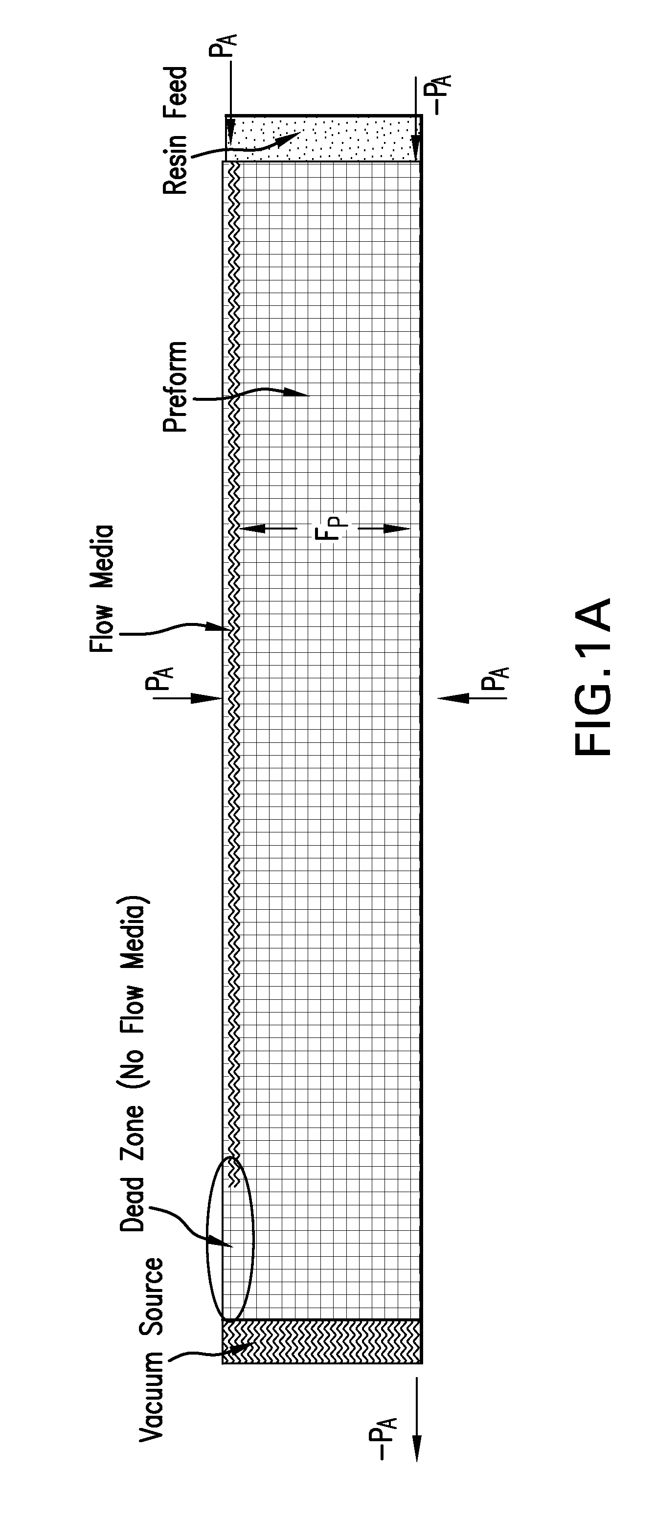
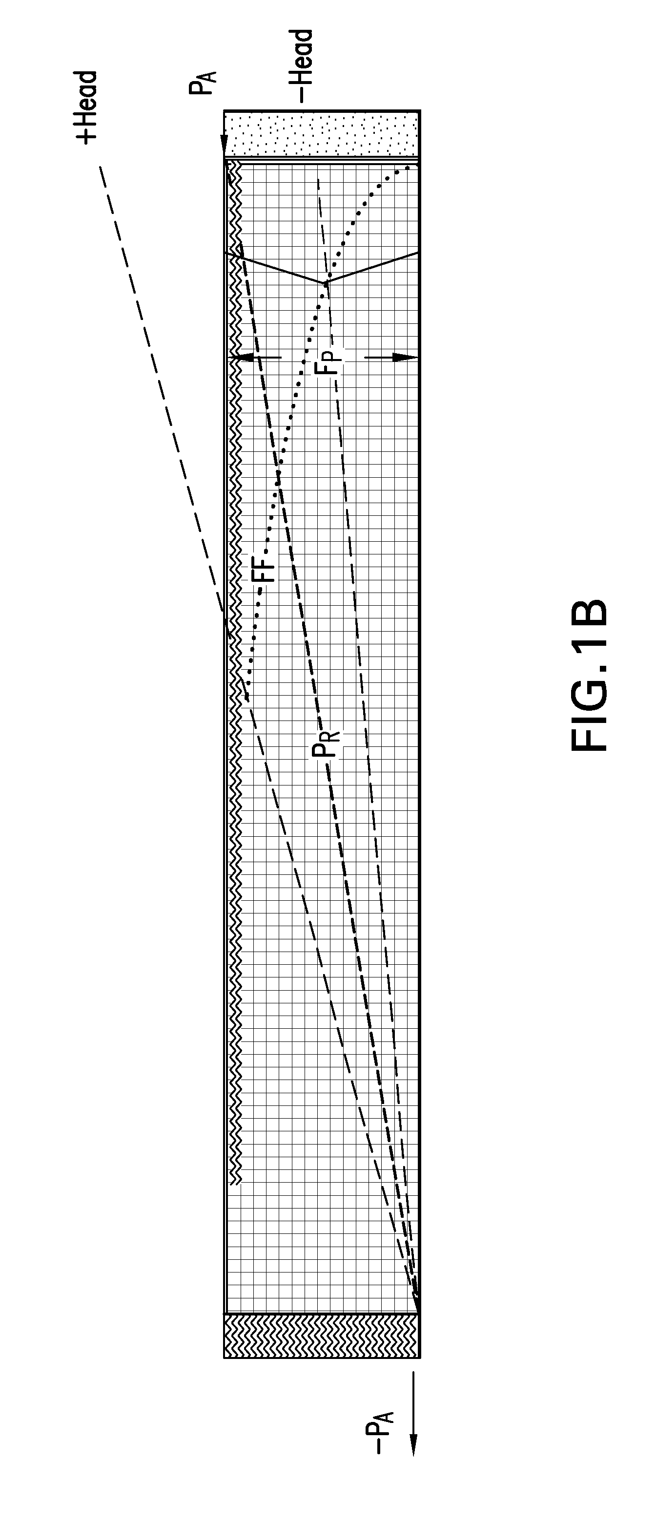
While relatively inexpensive, wet layup fabrication typically produces composites having low fiber volume fractions and high porosity, which reduce the overall strength and quality of the composite so manufactured.
In contrast, while fabrication of composites through prepregging can achieve higher fiber volume fractions and reduced void content, the cost to fabricate prepregs is much higher.
Furthermore, the shelf life of the frozen prepregs is limited, due to continued polymerization, even in the frozen state, and handling must be carefully controlled.
Fabrication of composites by infusion and other closed mold processes, such as RTM, is also expensive, owing to the high cost to obtain and maintain the requisite tooling and liquid injection systems.

Method used


Image

  • Constant pressure infusion process for resin transfer molding
  • Constant pressure infusion process for resin transfer molding
  • Constant pressure infusion process for resin transfer molding

Examples


example 1

[0072]A single part epoxy resin system (Cytec Engineered Materials CYCOM 977-20) was used, which exhibits a very high viscosity at room temperature but has a low viscosity and long pot life at an elevated temperature. This resin was initially packaged into polypropelene plastic bags in quantities ranging from 250 grams to 1000 grams. These bags were heat sealed in such a manner that at one end there was a constriction allowing for insertion of a tube once cut. Polypropylene is an acceptable material for use in the desired cure cycle for CYCOM 977-20. This pre-packaged collapsible resin reservoir was then placed next to the preform on the tool and a feed line was connected from the reservoir to the feed line of the preform. The preform was bagged per a typical infusion scheme which incorporates a resin bleed system and a vacuum bag was placed over the preform and the resin reservoir as shown in FIG. 2A. The preform was debulked and compacted and then checked for leaks and readied for...

example 2

[0074]The same single part epoxy resin and resin bags were used as in Example 1 to infuse a much larger component. The component was set up and bagged according to FIG. 2B which incorporated a standard infusion bagging scheme with a resin bleed system. To infuse this component, multiple resin reservoirs were used that were linked or daisy-chained together in order to deliver adequate resin and completely infuse the preform. The process yielded aerospace quality laminates with minimum variation.

example 3

[0075]The same single part epoxy resin used in Examples 1-2 was used to make a more complicated component that incorporated some stiffening members. The component was set up with floating cauls to support the stiffeners and was bagged according to FIG. 2C. As shown, the resin reservoirs were located next to the floating cauls in order to feed resin in the desired location. The process again yielded an aerospace quality laminate with minimum variation.


PUM

PropertyMeasurementUnit
temperatureaaaaaaaaaa
vacuum pressureaaaaaaaaaa
pressureaaaaaaaaaa

Abstract

Methods and apparatuses for making PMC's and composites include an infusing step wherein the resin reservoir and the preform are maintained under substantially the same vacuum pressure during the infusing step or the associated structure associated with the maintenance. Substantially the same vacuum pressure may be accomplished using a collapsible resin reservoir that is enclosed within or external to the vacuum bagging assembly of the fiber preform. This method results in a maximum achievable vacuum compaction pressure and simplified resin infusion process. This process may be used to manufacture prepregs and aerospace grade fiber reinforced resin composites, also disclosed herein, that have fiber volume, void content and laminate quality that meets or exceeds those made using an autoclave.

Description

BACKGROUND OF THE INVENTION[0001]1. Field[0002]Embodiments of the present disclosure pertain to resin infusion processes and, in particular, to resin infusion processes for the fabrication of fiber reinforced composites employing vacuum pressure processing.[0003]2. Description of the Related Art[0004]Fiber-reinforced polymer matrix composites (PMCs) are high-performance structural materials that are commonly used in applications requiring resistance to aggressive environments, high strength, and / or low weight. Examples of such applications include aircraft components (e.g. tails, wings, fuselages, propellers), boat hulls, and bicycle frames. PMCs comprise layers of fibers that are bonded together with a matrix material, such as a polymer resin. The fibers reinforce the matrix, bearing the majority of the load supported by the composite, while the matrix bears a minority portion of the load supported by the composite and also transfers load from broken fibers to intact fibers. In thi...

Claims


Application Information

Patent Timeline
Patent Type & Authority Applications(United States)
IPC IPC(8): B32B5/22B29C70/36
CPCB29C43/3642B29L2031/087B29C2043/3644B29C70/443B29C70/544Y10T428/249986B29C43/10B29C43/12B29C43/36B29C70/44
Inventor SMITH, MITCHELL DAVIDDOYLE, MARC
Owner CYTEC TECH CORP
Learn More