
Repeater equipped with attenuator and variable attenuation method in the repeater and system for remotely managing the same

Inactive Publication Date: 2010-05-13
KT CORP
View PDF3 Cites 9 Cited by
  • Summary
  • Abstract
  • Description
  • Claims
  • Application Information

AI Technical Summary

Benefits of technology

[0009]The present invention has been made in an effort to further provide a repeater having advantages of sharing a feeder of a link antenna even in a multi-band repeater and thus reducing an equipment investment cost.
[0010]The present invention has been made in an effort to further provide a remote management method and system having advantages of reducing a cost and a time for maintenance of a repeater by remotely adjusting an attenuation value of an attenuator of the repeater without directly going out to the location.Technical Solution

Problems solved by technology

Therefore, there is a problem that much time and cost are required in maintenance of the repeater.
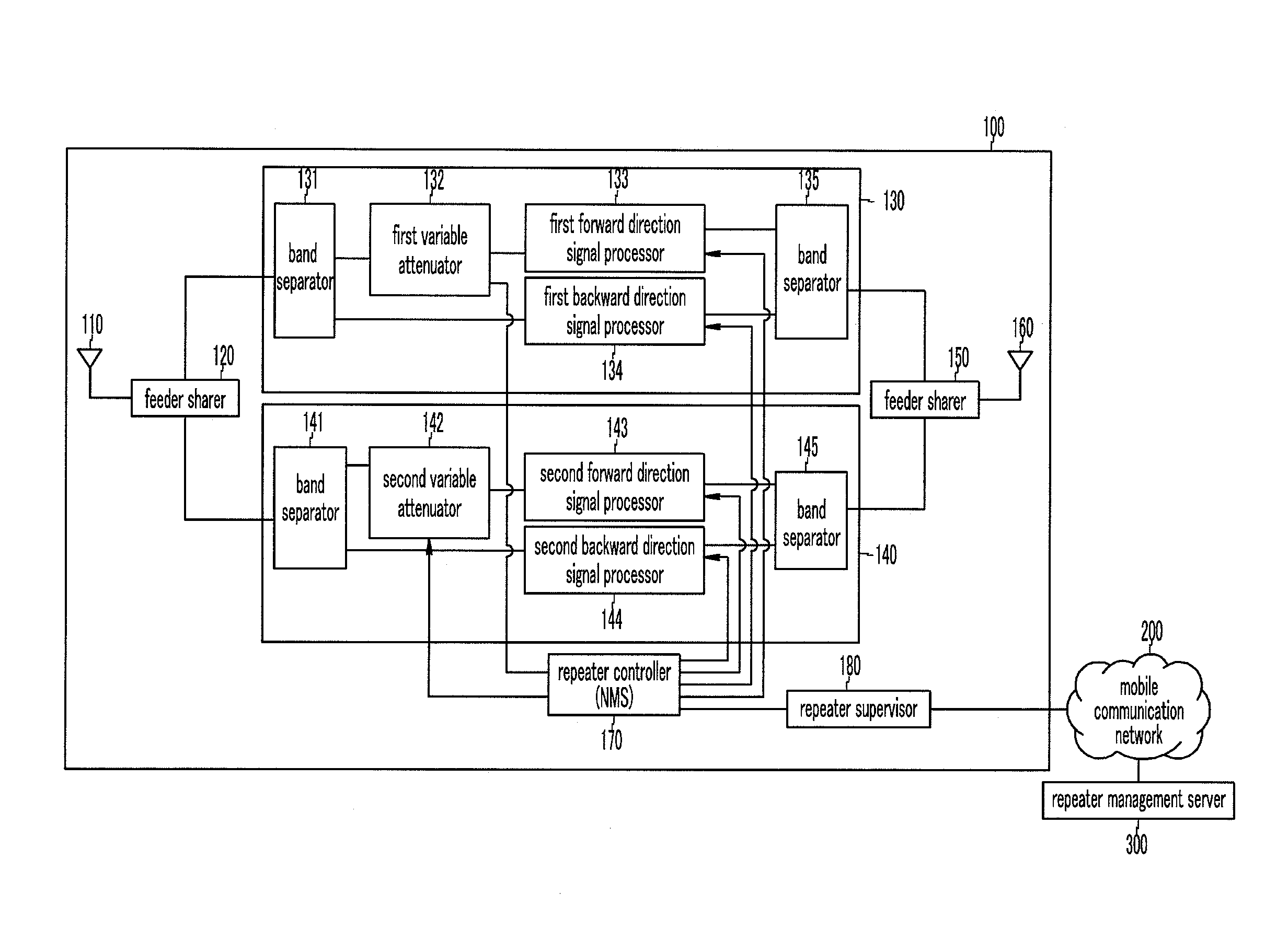
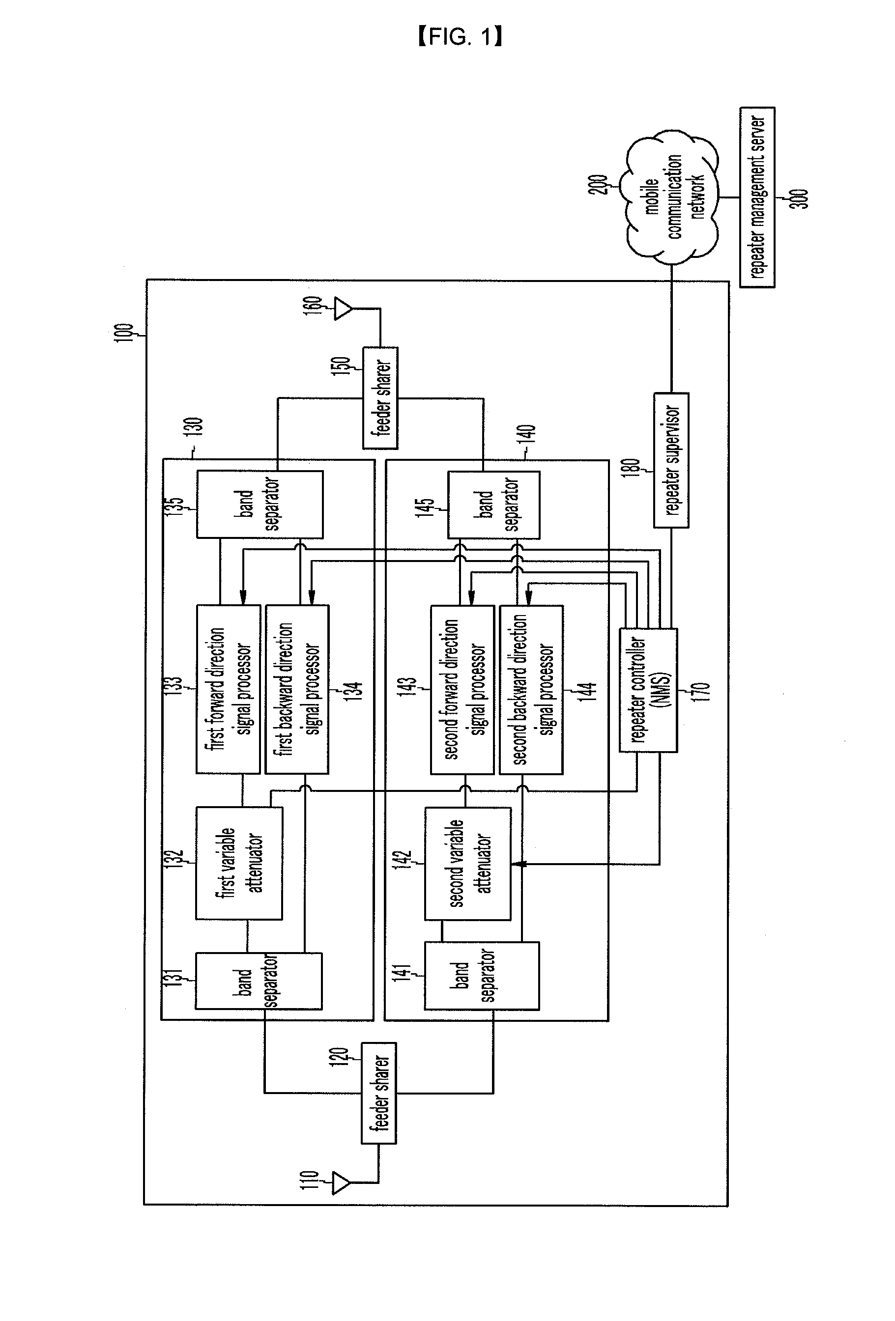
Further, in a multi band repeater, because intensity of an input signal that is received according to each band is different, a plurality of attenuators for attenuating each intensity of a signal that is excessively input on a band basis is required.
Further, because the multi band repeater has different propagation loss on a band basis, when the multi band repeater shares a feeder for a link antenna, an excess input state or a low input state may be formed on a frequency band basis, whereby in the multi band repeater, there is a problem that it is difficult to share a feeder of the link antenna.

Method used


Image

  • Repeater equipped with attenuator and variable attenuation method in the repeater and system for remotely managing the same
  • Repeater equipped with attenuator and variable attenuation method in the repeater and system for remotely managing the same
  • Repeater equipped with attenuator and variable attenuation method in the repeater and system for remotely managing the same

Examples


Embodiment Construction

Technical Problem

[0008]The present invention has been made in an effort to provide a repeater having an attenuator having advantages of adjusting an attenuation value according to propagation characteristics of each band input signal.

[0009]The present invention has been made in an effort to further provide a repeater having advantages of sharing a feeder of a link antenna even in a multi-band repeater and thus reducing an equipment investment cost.

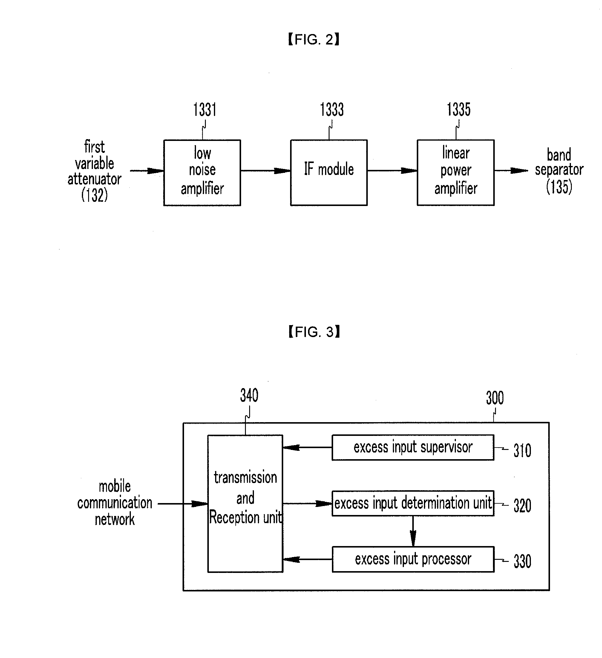
[0010]The present invention has been made in an effort to further provide a remote management method and system having advantages of reducing a cost and a time for maintenance of a repeater by remotely adjusting an attenuation value of an attenuator of the repeater without directly going out to the location.

Technical Solution

[0011]An exemplary embodiment of the present invention provides a repeater that relays a signal between a base station and a service side, including: a forward direction signal processor that performs an amplifying and...


PUM


Abstract

A repeater relays at least one frequency band signal between a base station and a service side, includes at least one variable attenuator for variably attenuating each of at least one frequency band signal, variably attenuates an input signal that is received from the base station through the variable attenuator, and transfers the input signal to the service side. Further, a remote management system of the repeater communicates through the repeater and a mobile communication network and includes a repeater management server for requesting to change an attenuation value of the variable attenuator to the repeater when the input signal is an excess input signal. When an excess input signal is received in the repeater using the repeater and a remote management system of the repeater, an input signal level of the repeater can be remotely adjusted and an input signal level of the repeater can be managed without directly going out to the location, so that a maintenance cost of the repeater can be reduced.

Description

TECHNICAL FIELD[0001]The present invention relates to a repeater having an attenuator and a method and a system for remotely managing the same. More particularly, the present invention relates to an attenuator for attenuating input signal intensity of a repeater and a remote management method and system for remotely controlling the same.BACKGROUND ART[0002]A repeater is a device that receives a signal of a base station and relays the signal to a mobile communication terminal, and that is used for extending coverage in a mobile communication system. In general, the repeater receives a weak signal that is transmitted from a base station through a link antenna, amplifies the received signal, and then transmits the signal to a mobile communication terminal through a service antenna.[0003]Nowadays, a multi band repeater that receives and relays a signal having a plurality of different frequency bands has been developed and used in the location. For example, because a dual band repeater t...

Claims


Application Information

Patent Timeline
IPC IPC(8): H04B7/14
CPCH04B7/15535H04B7/15H04B15/00
Inventor JIN, YANG-KYUKIM, JAE-KONCHOI, YONG-WON
Owner KT CORP
Learn More