
Generating laser pulses of prescribed pulse shapes programmed through combination of separate electrical and optical modulators

a laser pulse and pulse shape technology, applied in laser optical resonator construction, laser details, semiconductor lasers, etc., can solve the problems of poor cross-wafer or wafer thickness uniformity, non-optimal thickness, and over-cratering, and achieve the effect of fast ris

Inactive Publication Date: 2010-05-13
ELECTRO SCI IND INC
View PDF6 Cites 41 Cited by
  • Summary
  • Abstract
  • Description
  • Claims
  • Application Information

AI Technical Summary

Benefits of technology

The patent describes a device that can create laser pulses with a specific shape and duration. This is done by combining electrical and optical modulation of the laser pulse. The device allows for power scaling and the creation of harmonics at shorter wavelengths. It is a more efficient and reliable alternative to existing methods and can be used at a variety of wavelengths. Overall, the device has improved efficiency and flexibility in creating shaped laser pulses.

Problems solved by technology

Use of a traditional Gaussian-shaped laser pulse having a 5-20 ns pulse width and a sloped, gradually rising front edge in link processing tends to cause an “over crater” in the passivation layer, especially if its thickness is too large or is uneven.
Difficulty in maintaining wafer-level process control of the passivation layer during IC fabrication may result in non-optimal thickness and poor cross-wafer or wafer-to-wafer thickness uniformity.
However, the center wavelength of the semiconductor diode tends to drift with small changes in temperature resulting from the change in pulse shape, which temperature drift may adversely affect downstream solid-state amplifiers and harmonic generation.
However, generating a pulsed laser from a CW light beam is fairly inefficient, and thus requires more amplification.
Because such a low peak-power signal may be influenced by noise, which causes pulse-to-pulse instability, the two modulators are preferably synchronized to maintain pulse stability and energy stability, thereby adding further complexity and cost.

Method used


Image

  • Generating laser pulses of prescribed pulse shapes programmed through combination of separate electrical and optical modulators
  • Generating laser pulses of prescribed pulse shapes programmed through combination of separate electrical and optical modulators
  • Generating laser pulses of prescribed pulse shapes programmed through combination of separate electrical and optical modulators

Examples


Embodiment Construction

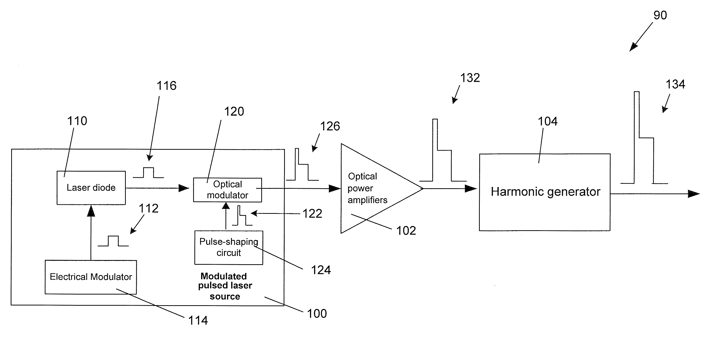
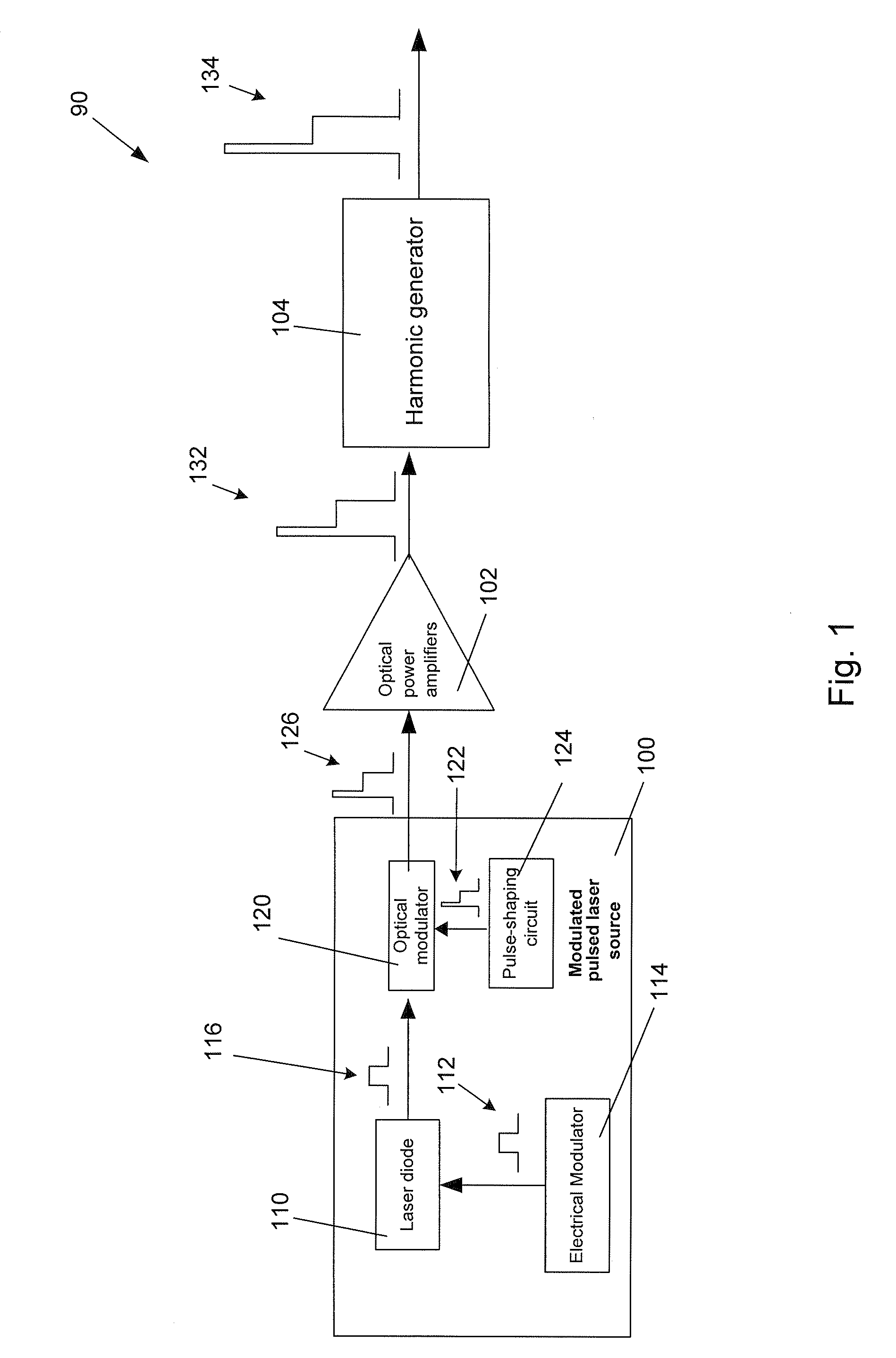
[0021]FIG. 1 shows a laser pulse-shaping generator 90 with the desired operating and performance characteristics discussed above. Pulse-shaping generator 90 is constructed of a modulated pulsed laser source 100 that produces a prescribed tailored laser pulse for amplification by a set of optical power amplifiers 102 and for wavelength conversion by a harmonic generator 104.

[0022]Modulated pulsed laser source 100, such as a semiconductor laser, is preferably composed of a high-speed distributed feedback (DFB) seed laser diode 110 that is modulated by a seed pulse signal 112 produced by an electrical modulator 114 to provide at a high repetition rate a series of seed laser pulses 116. In a preferred implementation, seed pulse signal 112 represents a series of seed pulses 116. An optical modulator 120 receives and, in response to gating electrical control signal pulses 122 that are produced by a high-speed programmable pulse-shaping circuit 124 and are synchronized to seed pulse signal...


PUM


Abstract

A programmable laser pulse combines electrical modulation of the pulse frequency and optical modulation of the pulse shape to form laser pulses of prescribed pulse shapes. A prescribed pulse shape features high peak power and low average power. The laser system disclosed also allows for power-scaling and nonlinear conversions to other (shorter or longer) wavelengths. The system provides an economical reliable alternative to using a laser source with high repetition rates to achieve shaped pulses at a variety of wavelengths. The combinatorial scheme disclosed is inherently more efficient than existing subtractive methods.

Description

COPYRIGHT NOTICE[0001]© 2008 Electro Scientific Industries, Inc. A portion of the disclosure of this patent document contains material that is subject to copyright protection. The copyright owner has no objection to the facsimile reproduction by anyone of the patent document or the patent disclosure, as it appears in the Patent and Trademark Office patent file or records, but otherwise reserves all copyright rights whatsoever. 37 CFR §1.71(d).TECHNICAL FIELD[0002]The present disclosure relates to pulsed fiber lasers and solid-state laser amplifiers from which tailored laser pulses propagate for use in laser micromachining applications and, in particular, to a highly efficient laser pulse-shaping generator emitting tailored laser pulses with prescribed pulse shapes programmed through a combination of separate electrical and optical modulators.BACKGROUND INFORMATION[0003]After manufacture of a semiconductor memory array chip is complete, integrated circuit (IC) patterns on an exposed ...

Claims


Application Information

Patent Timeline
Patent Type & Authority Applications(United States)
IPC IPC(8): H01S3/10H01S5/12
CPCH01S3/06754H01S3/2316H01S3/2383H01S5/12H01S5/0092H01S5/0428H01S5/005H01S3/10
Inventor PENG, XIAOYUANBARSIC, DAVIDJORDENS, WILLIAM J.WANG, QI
Owner ELECTRO SCI IND INC
Learn More