
Frequency stabilization technique for self oscillating modulator

a self-oscillating, modulator technology, applied in the direction of pulse automatic control, electric variable regulation, electrial characteristics varying frequency control, etc., can solve the problem of low noise and distortion value, interference with (audio) signal, switching noise created on the supply line,

Inactive Publication Date: 2006-07-11
DIALOG SEMICONDUCTOR GMBH
View PDF12 Cites 15 Cited by
  • Summary
  • Abstract
  • Description
  • Claims
  • Application Information

AI Technical Summary

Benefits of technology

"This patent describes a method for controlling the frequency of self-oscillating modulators, which is currently not constant and varies with input signal amplitude and power supply. The invention provides a continuous-time \"smooth\" mode to measure and correct the pulse frequency, and a discrete binary \"switching\" mode to select between two threshold correction signals based on the hysteretic comparator's output phase. The method uses a switched capacitor circuit technique and a low pass filter to produce the two threshold correction values. The technical effect of this invention is to provide a more effective frequency control method for self-oscillating modulators without producing significant extra distortion."

Problems solved by technology

Using a self oscillating (or hysteretic) modulator type results in very low noise and distortion values.
The moving frequency (Fp) can create several problems: with large input signal amplitude, i.e. per high modulation depths Fp becomes very low and may interfere with the (audio) signal.
Further the switching noise created on the supply line disturbs other circuits and can't be filtered effectively, due to the wide frequency range.

Method used


Image

  • Frequency stabilization technique for self oscillating modulator
  • Frequency stabilization technique for self oscillating modulator
  • Frequency stabilization technique for self oscillating modulator

Examples

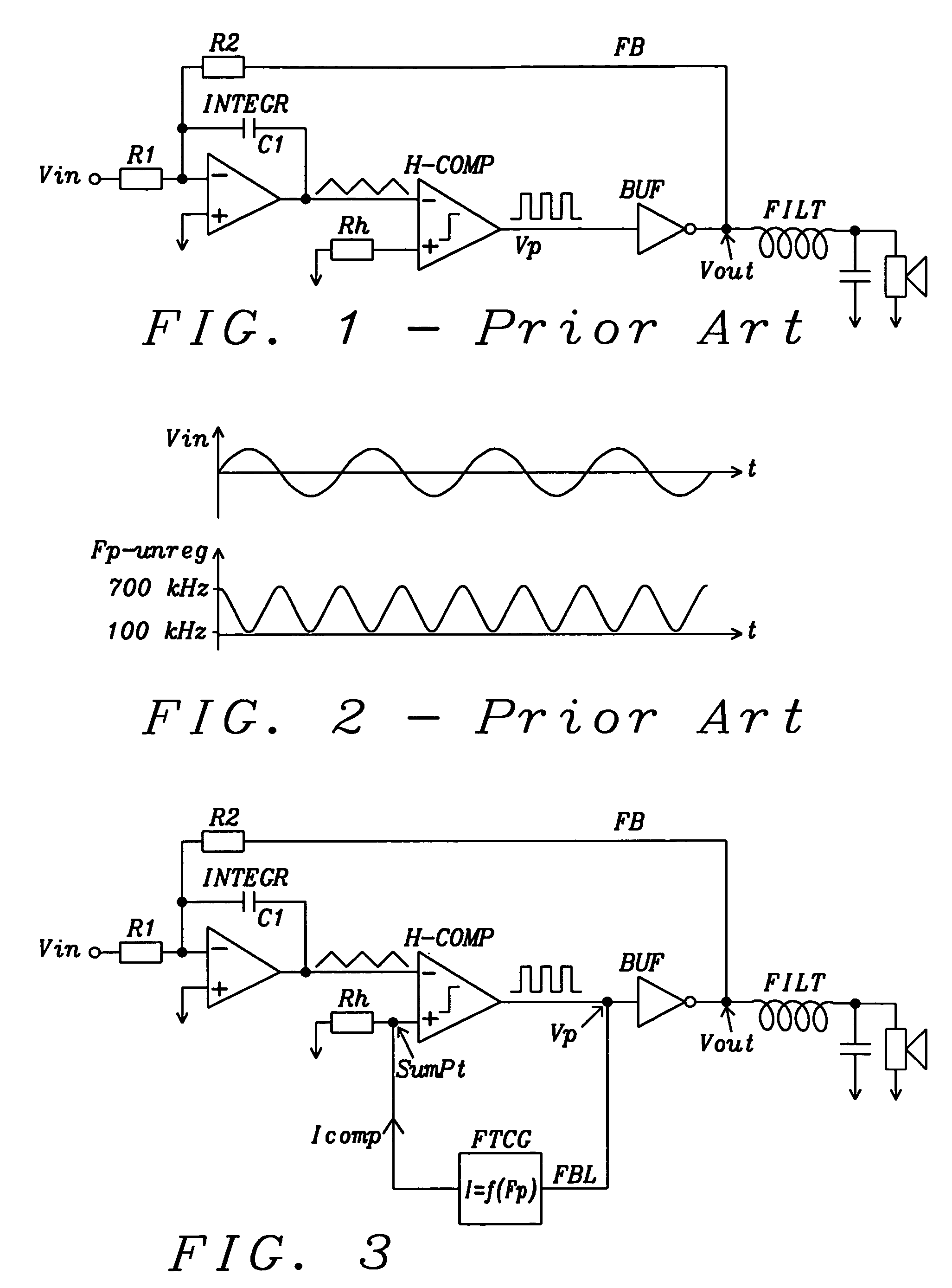

Embodiment Construction

[0029]It is an objective of the disclosed invention to provide an effective frequency control method for self-oscillating modulators which does not produce significant extra distortion.

[0030]Actual self oscillating pulse width modulators have disadvantages as the switching frequency is not constant, but varies significantly with input signal amplitude, output power and with supply voltage. As they typically operate in the range of several hundred kHz, they often interfere with AM-radio frequencies.

[0031]A typical self-oscillating pulse width modulator comprises an integrator, integrating the input signal, a hysteretic comparator, typically, but not necessarily followed by a buffer circuit and a feedback signal path, returning the output signal pulses to the integrator. The self oscillating (or hysteretic) modulator type benefits from theoretically infinite loop gain, resulting in very low noise and distortion values. Compared to the conventional PWM type (which uses some kind of ext...


PUM


Abstract

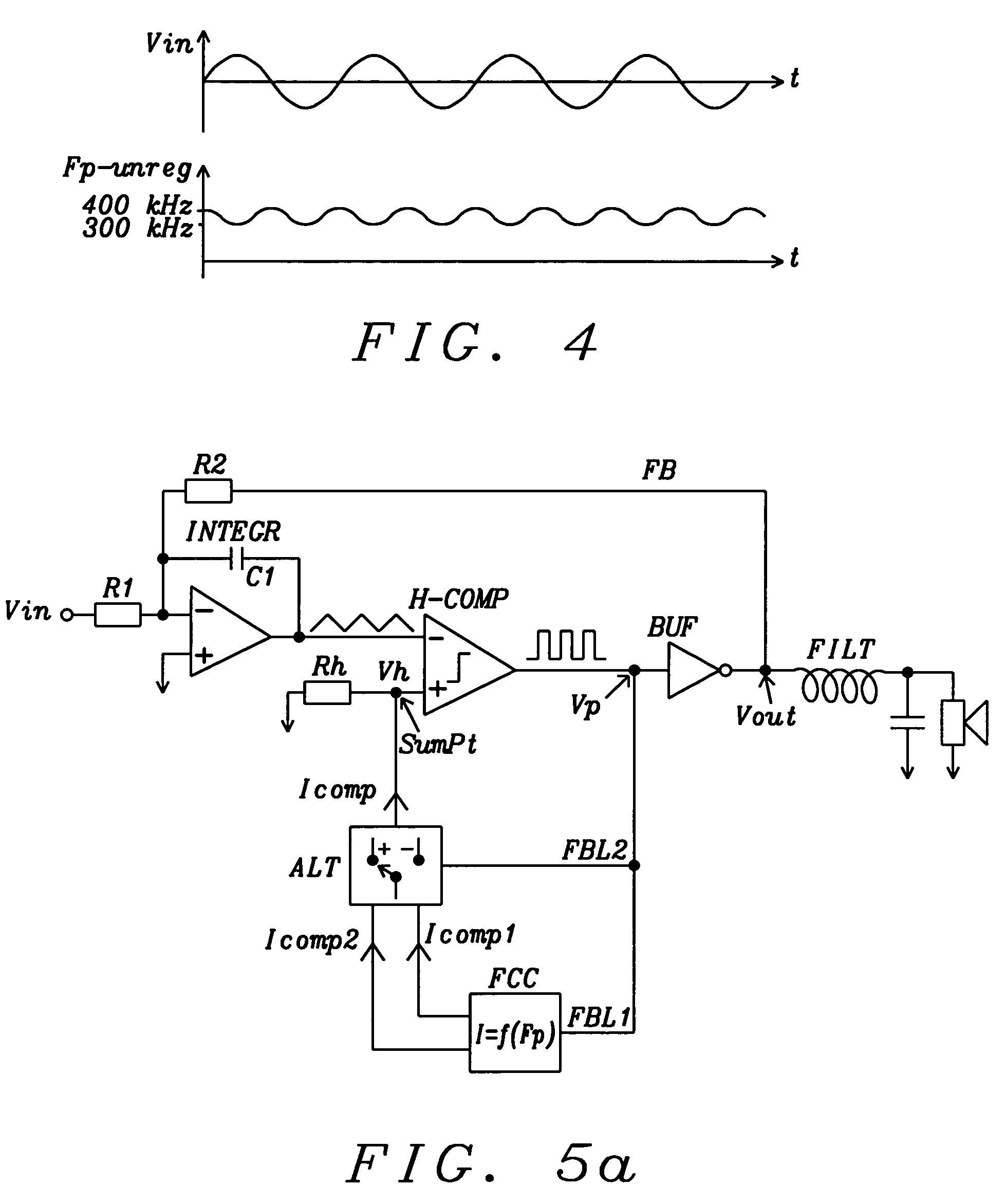
With self oscillating pulse width modulators, using a hysteretic comparator to change the output duty cycle according to the input signal, as often used for example for Class-D amplifiers or switching regulators, the frequency varies with output power and supply voltage. The disclosed invention presents a method to drastically reduce the frequency variation by introducing the combination of an analog and a digital feedback loop to shift the hysteretic threshold, ideally by providing a single absolute value, which is proportional to the pulse frequency and by alternating the polarity of shifting the hysteretic threshold, based on the actual output pulse phase.

Description

BACKGROUND OF THE INVENTION[0001](1) Field of the Invention[0002]The present invention relates to self-oscillating pulse width modulators, using a hysteretic comparator to change the output duty cycle according to the input signal.[0003](2) Description of Prior Art[0004]A pulse width modulator (PMW) creates an output square wave where the duty cycle depends on its Input signal. PWM's are widely used within e.g. Class-D amplifiers or switching voltage regulators, where the output load is switched either to the negative or the positive supply, by simple MOSFET switches. Using a self oscillating (or hysteretic) modulator type results in very low noise and distortion values. However, compared to the conventional PWM type with fixed (external) clock, the switching frequency is not constant, but varies significantly with input signal amplitude, output power and with supply voltage.[0005]FIG. 1 shows one conceptual circuit diagram of a self-oscillating pulse width modulator and FIG. 2 demo...

Claims


Application Information

Patent Timeline
Patent Type & Authority Patents(United States)
IPC IPC(8): H02M1/12H03B5/20H02M1/00
CPCH03M1/50H03F2200/351
Inventor EBERLEIN, MATTHIAS
Owner DIALOG SEMICONDUCTOR GMBH
Learn More