
Multi power sourced electric vehicle

Active Publication Date: 2010-05-06
AUCKLAND UNISERVICES LTD
View PDF6 Cites 267 Cited by
  • Summary
  • Abstract
  • Description
  • Claims
  • Application Information

AI Technical Summary

Benefits of technology

[0028]Preferably, each ferromagnetic slab is spaced apart from the backplate by a thermally conductive and mechanically insulating material so as to allow the transfer of heat there between and protect the slab from mechanical shock. According to one embodiment, each slab may be spaced apart from the backplate using foam or rubber pads. The material making up the slabs is brittle and such steps serve to prevent cracking in the slabs caused by rapid temperature changes and also due to mechanical stresses exerted on the IPT pad.
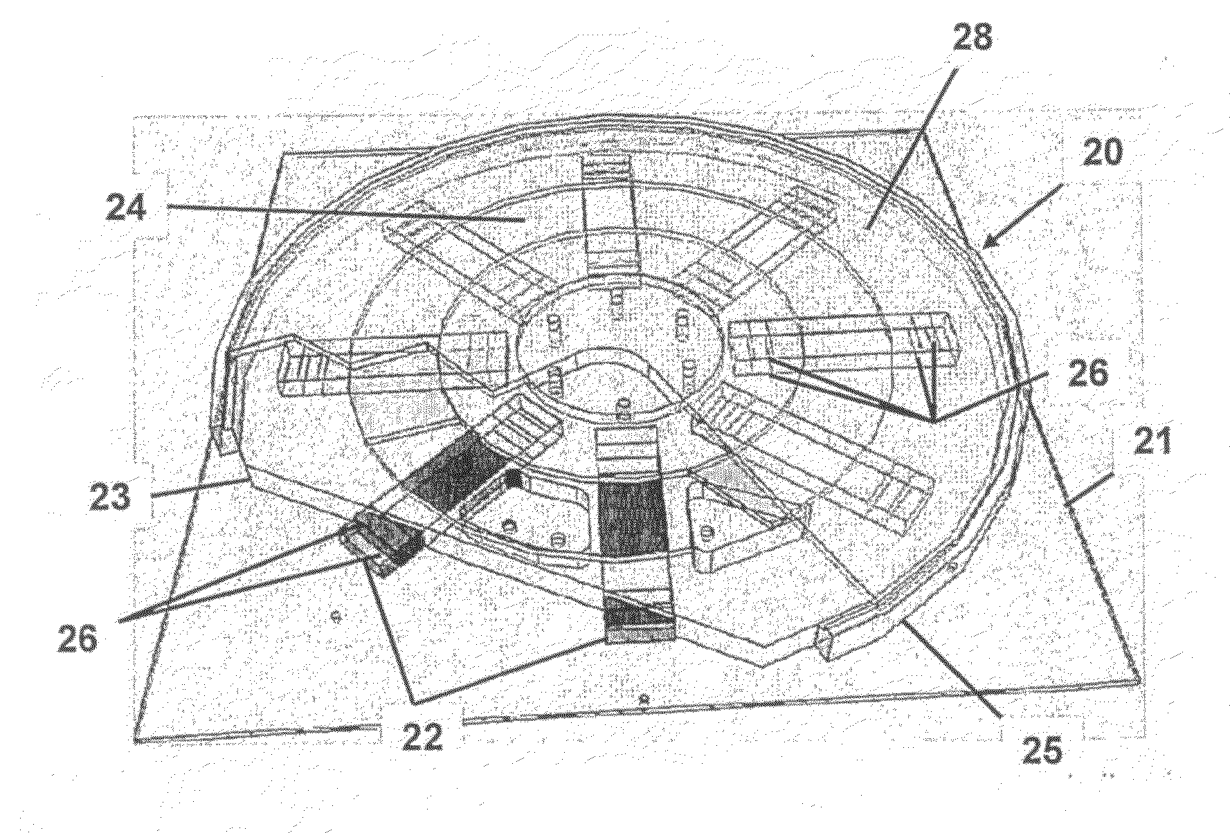
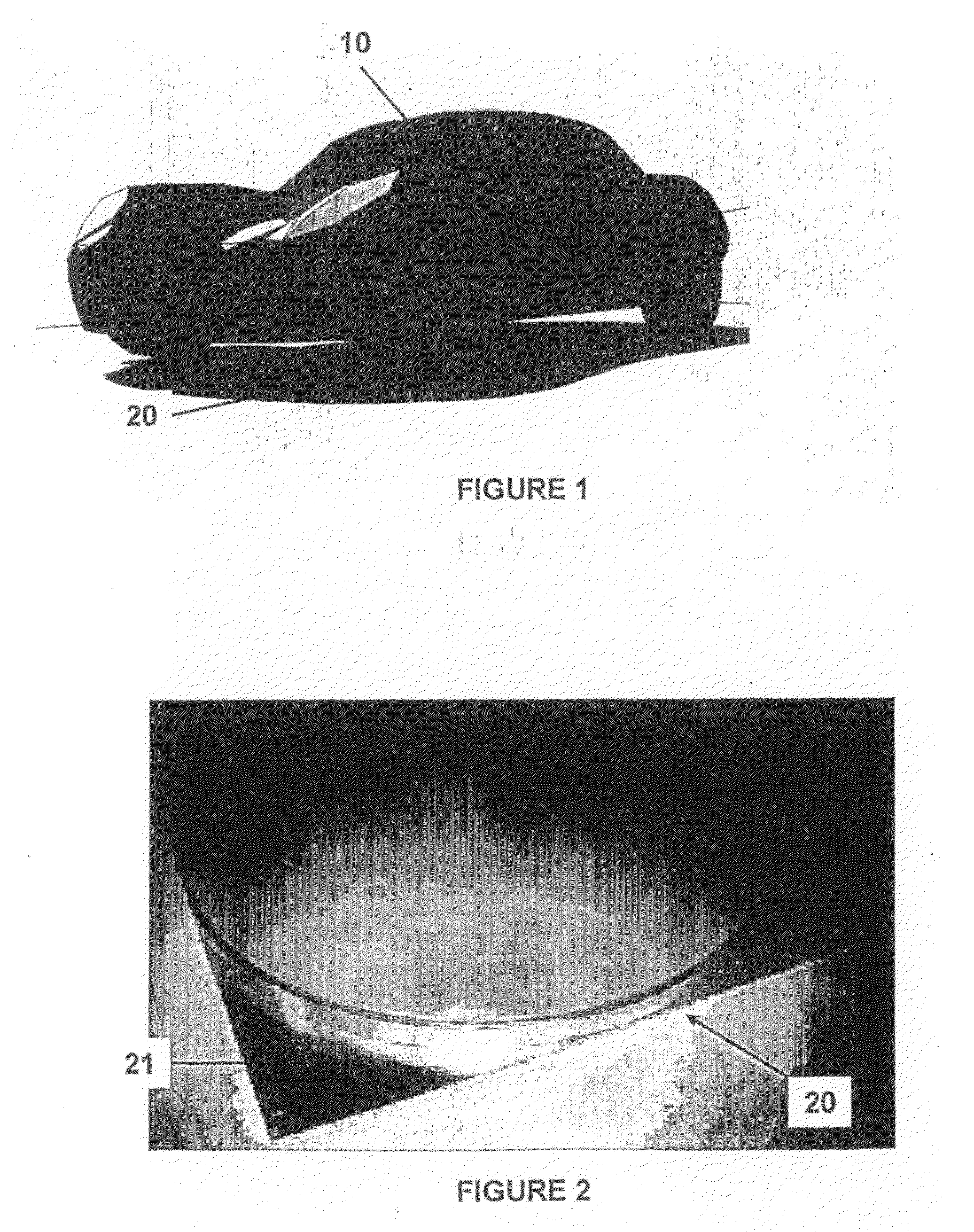
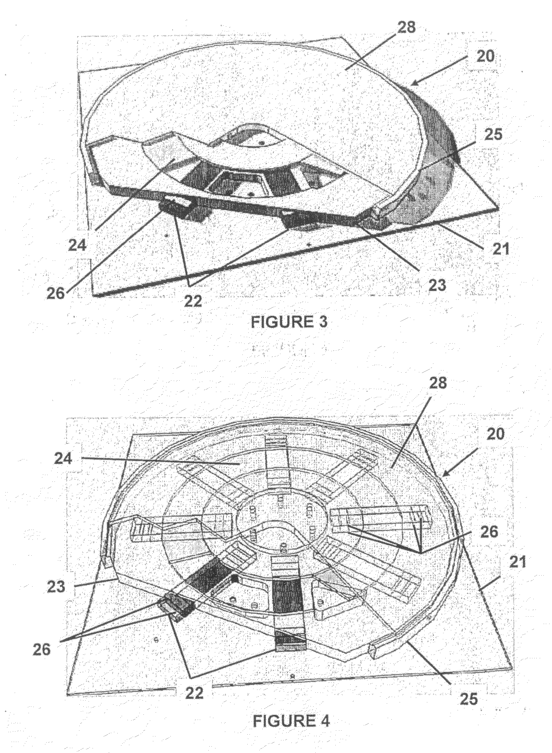
[0038]The IPT pad according to the first aspect provides for improved performance in use by channelling the flow of flux from the charging pad. More particularly, the backplate and the shield member serve to direct flux upwards from the plane of the backplate with less splay of flux in and parallel to the plane of the backplate. This not only improves the inductive coupling but also reduces the chance that any undesired objects will be subjected to the induced fields during use. It is important to note that if this leakage is not controlled, it can lead to damage of such objects. For example, in the case of an electric vehicle, such leakage may result in the wheel bearings eroding.
[0043]Preferably, the first means for coupling comprises a socket electrically coupled to the battery, wherein power is transferred by plugging a cable connected to the high power electrical supply into the socket. Thus, electrical energy may be rapidly transferred to the battery using the first means for coupling, resulting in rapid charging.
[0046]The use of IPT avoids the need for a user to plug in a cable for opportunity charging, including when a vehicle is parked overnight. Additionally or alternatively, a second socket may be provided or the first socket adapted, if required, so that the battery may be connected to a lower power supply using a cable. Again, in the alternative, the second socket may be substituted by a plug configured to mate with a socket connected to the lower power supply. Such embodiments provide for improved flexibility in that, where provided and where time permits, the battery may be charged using IPT. If rapid charging is required and a high power supply is available, the battery may be connected thereto. However, there remains the possibility that a battery will require charging where neither an IPT charging pad or a high power supply is available. A user could, perhaps, put the charging pad inside the vehicle when in transit so that, as required, it could be removed from the vehicle, appropriately positioned and used for charging. This is possible because embodiments of the invention involving IPT preferably work to widely available household voltages but this is inconvenient.
[0065]Any energy source may be used by the generator(s) to generate electrical energy. However, according to preferred embodiments, a renewable energy source is used. Through use of the control means, it is possible to overcome problems associated with the fluctuable nature of power generated from renewable sources and enhance the stability of the network by varying the power supplied to the battery so that the power demand on the network better matches the available power. These benefits are more marked according to embodiments of the system in which the network is coupled to a plurality of batteries of a corresponding plurality of electric or hybrid electric vehicles.
[0078]According to an eleventh aspect of the invention there is provided a method of controlling load demand on an electricity network, the method comprising: allowing the frequency of power supplied by the network to vary; monitoring the frequency of power supplied by the network; and increasing or reducing the power consumed by the load dependent on the frequency.

Problems solved by technology

In the development of pure electric vehicles (i.e., those powered solely by electricity as opposed to hybrid vehicles), there are a number of problems to be solved before these vehicles can gain widespread acceptance.
These include the limited range compared with more conventionally fuelled vehicles, the inconvenience of having to remember to recharge a vehicle (even if it is possible to do so at the user's premises or home) and the severe restrictions that occur should the vehicle not be charged.
Many problems with electric vehicles stem directly from the battery used to store energy to power the vehicle.
Virtually all battery types must be charged at a rate that is less than the allowable discharge rate, they have a limited capacity, and their cycle life is not great.
Thus, it takes quite a long time to charge a vehicle, the time between charges is shorter than ideal, and the functionality of the battery declines rapidly with age.
However, if the available range is exceeded or the battery has not been sufficiently charged, the driver and passengers may be left stranded, there will likely be a recovery fee, the battery will need to be fully charged over a longer period of time than a conventional charge cycle and, when using conventional batteries, these will almost certainly be degraded such that their available capacity is permanently reduced from what it was previously.
In perhaps a more serious situation where circumstances call for the vehicle to be taken on a long trip, there is little that can be done.
For these reasons conventional pure electric vehicles have not met all of the modern requirements for a passenger transport vehicle.
Moreover, the use of IPT obviates the need for a user to manually connect a cable to the battery.

Method used


Image

  • Multi power sourced electric vehicle
  • Multi power sourced electric vehicle
  • Multi power sourced electric vehicle

Examples


Embodiment Construction

[0088]Embodiments of the invention provide for a multi-source electric vehicle that is able to operate in most situations that may occur in terms of types, length and frequency of trips. References to “multi-source electric vehicles” are used to refer to electric vehicles embodying or capable of operating with embodiments of the present invention where the batteries and / or cells used to power the vehicle may be charged using various electrical power sources. Embodiments of the invention provide all of the advantages of a plug-in electric vehicle in that it can be recharged ‘at home’ overnight but, according to preferred embodiments, it does so without the disadvantage of requiring a cable to be plugged in. More particularly, according to preferred embodiments, a charging pad is preferably provided on the floor where the vehicle is usually parked, such as in the floor of a user's garage. While the vehicle is parked, the charging pad transfers energy to the vehicle's battery by Induct...


PUM


Abstract

An inductive power transfer (IPT) pad and system for the charging of electric and hybid electric vehicles. The batter of such a vehicle can be selectively coupled to a high power electrical supply for fast charging or a lower power electrical supply for charging using IPT. The batteries of the vehicles are used in a system to control the load demand in an electricity network through variations of the frequency of power supplied.

Description

FIELD OF THE INVENTION[0001]The present invention relates to an Inductive Power Transfer (IPT) pad, a system, method and means for charging a battery of an electric vehicle using multiple power sources and an electric vehicle powered by said battery. More particularly, the invention relates to charging the battery for an electric vehicle selectively using a high power source for charging at a high rate or a lower power source for charging at a lower rate.BACKGROUND[0002]In the development of pure electric vehicles (i.e., those powered solely by electricity as opposed to hybrid vehicles), there are a number of problems to be solved before these vehicles can gain widespread acceptance. These include the limited range compared with more conventionally fuelled vehicles, the inconvenience of having to remember to recharge a vehicle (even if it is possible to do so at the user's premises or home) and the severe restrictions that occur should the vehicle not be charged. These problems have...

Claims


Application Information

Patent Timeline
IPC IPC(8): H02J7/02H04B5/00
CPCB60L8/006B60L2270/147Y02T10/7005Y02T10/7083Y02T10/7088Y02T90/122Y02T90/128Y02T90/14H01F38/14Y02T90/121B60L53/12B60L53/60B60L53/11B60L53/51Y02T10/6269B60L53/124B60L53/126B60L53/62Y02T10/62Y02T10/7072Y02T90/12Y02T10/70B60L53/14B60L53/305B60L53/38B60L53/63B60L55/00B60L2250/16H01F27/363H02J7/0042H02J50/10H02J50/40H02J50/70H02J50/90H02J2310/48Y02E60/00Y02T90/16Y04S10/126B60L53/16B60Y2200/91B60L53/18H01F5/00H01F27/36
Inventor BOYS, JOHN TALBOTCOVIC, GRANT ANTHONY
Owner AUCKLAND UNISERVICES LTD
Learn More