
Light source device and projector

Active Publication Date: 2010-04-29
SEIKO EPSON CORP
View PDF12 Cites 32 Cited by
  • Summary
  • Abstract
  • Description
  • Claims
  • Application Information

AI Technical Summary

Benefits of technology

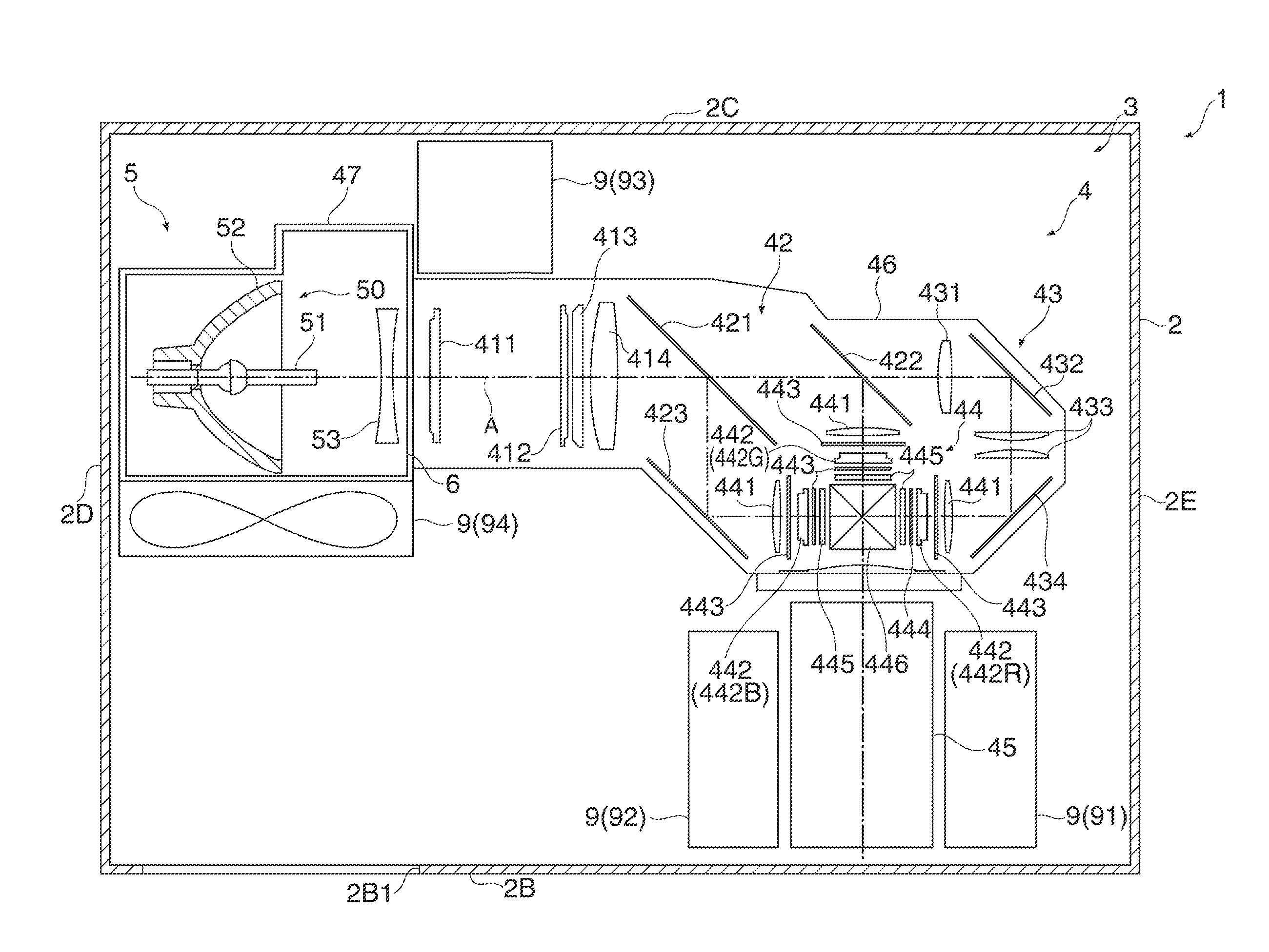
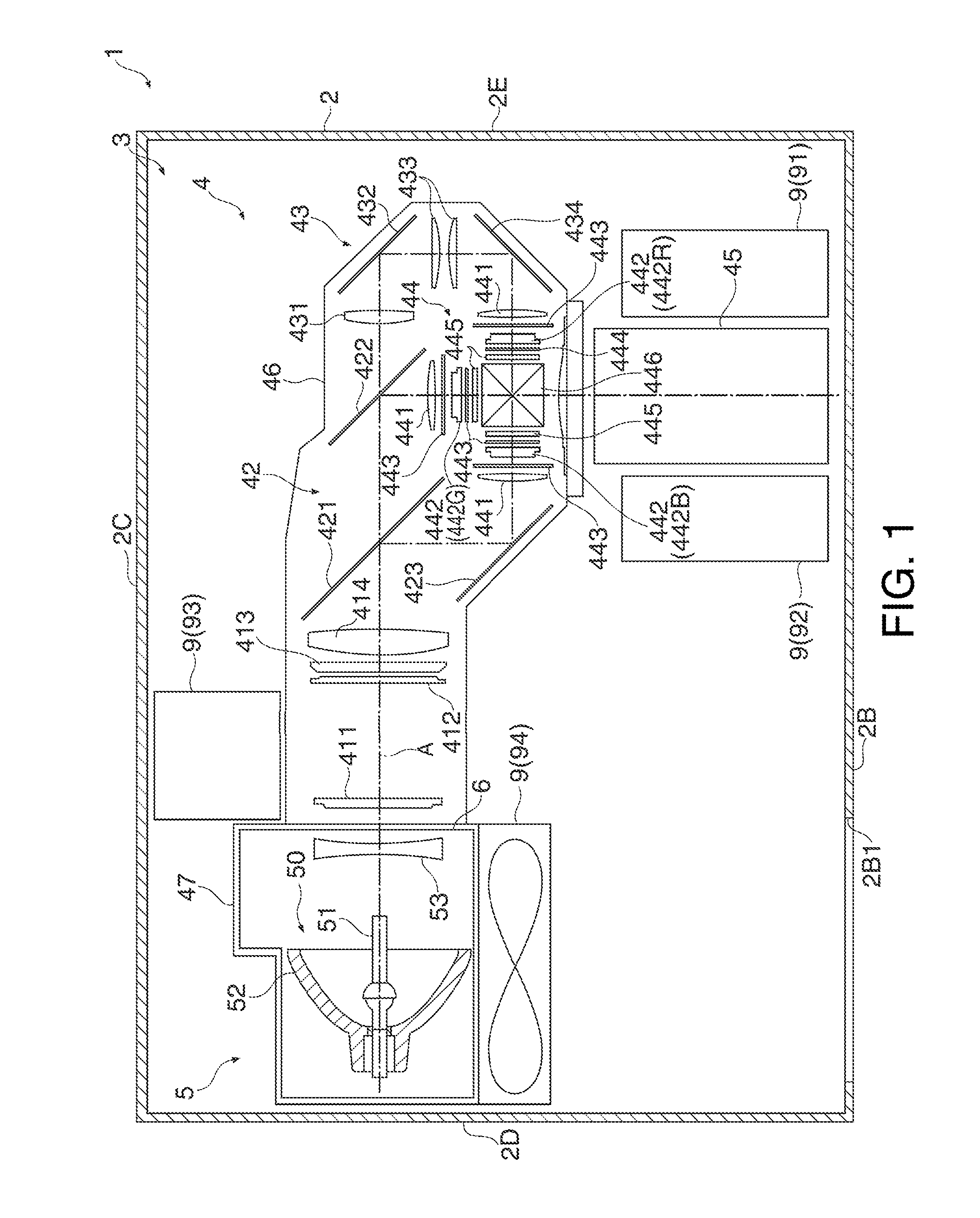
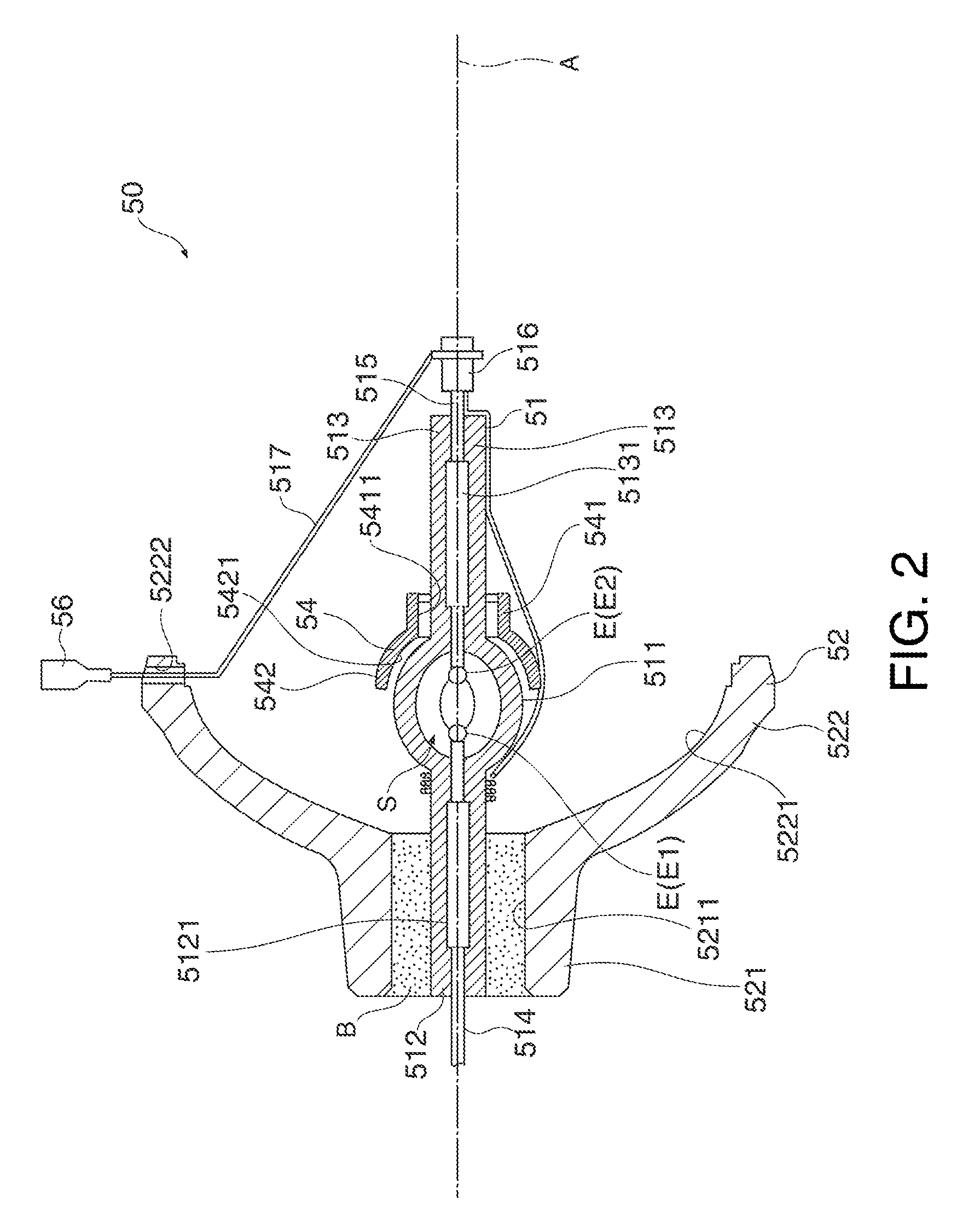
[0011]Since the duct unit is provided above the arc tube, the cooling air flowing within the duct unit is supplied to the upper region of the light emission portion. In this case, the upper region of the light emission portion can be positively cooled, and temperature difference between the upper region and the lower region can be reduced. Thus, deterioration of the arc tube can be prevented.
[0012]Accordingly, the upper region of the arc tube can be adequately cooled, and the life of the arc tube can be increased.
[0014]According to this structure, the first opening and the opening end of the first reflection mirror are positioned close to each other. In this case, cooling air can be supplied to the upper region of the light emission portion linearly from a short distance compared with a structure in which the first opening and the opening end of the first reflection mirror are positioned away from each other. Accordingly, cooling air can be securely supplied to the upper region of the arc tube.
[0016]According to this structure, the arc tube on the first sealing portion side can be cooled by cooling air flowing through the first opening, and the arc tube on the second sealing portion side can be cooled by cooling air flowing through the second opening. Thus, the entire area of the arc tube can be cooled, and the life of the arc tube can be further increased.
[0018]According to this structure, apart of light emitted from the light emission portion and not directly reaching the first reflection mirror is reflected by the second reflection mirror toward the first reflection mirror. Thus, utilization efficiency of light emitted from the light emission portion can be increased.
[0023]According to this structure, the same advantages as those of the light source device described above are provided, and the life of the light source device as well as the life of the arc tube are increased. Thus, the necessity for frequently replacing the light source device can be eliminated, and the labor for maintenance can be reduced.

Problems solved by technology

When high temperature condition of the upper region of the light emission portion continues, devitrification is easily caused.
In this case, the arc tube easily deteriorates.
Thus, in case of a structure including a flow path of cooling air for cooling the components of the projector as a path established before use, the light source device of the projector cannot be adequately cooled in the normal position or the suspended position depending on the installation condition.
In this case, the cooling air cannot reach the arc tube with appropriate inclination, and thus cannot be adequately supplied to the upper region of the arc tube.

Method used


Image

  • Light source device and projector
  • Light source device and projector
  • Light source device and projector

Examples


modified example

[0119]The invention is not limited to the embodiment described above, and it is therefore intended that changes and improvements may be made without departing from the scope and spirit of the invention.

[0120]According to the embodiment, the curved portion 61321 curved toward the upper side in the Y direction is formed on the inclined portion 6132 on the side opposite to the light emission side in the Z direction. However, the curved portion 61321 may be eliminated, for example. The flat portion 6132A may have an inclined portion curved toward the upper side in the Y direction in the vicinity of the opening 6134 on the side opposite to the light emission side in the Z direction. In this case, this inclined portion corresponds to an inclined portion in the appended claims. This applies to the inclined portion 6142 as well.

[0121]According to the embodiment, the wall portion 6135 is a wall extending in the direction perpendicular to the inner surface 624A of the upper surface 624. Howev...


PUM


Abstract

A light source device includes: an arc tube having a light emission portion; a first reflection mirror having a substantially concave surface for reflecting light emitted from the light emission portion; and a container which accommodates the arc tube and the first reflection mirror, wherein the container has a duct unit disposed above the arc tube. The duct unit includes a first opening open to the arc tube and disposed at a position shifted toward the traveling direction side from an opening end of the first reflection mirror, a wall portion which forms the edge of the first opening on the side opposite to the traveling direction side as a final end of the duct unit, and an inclined portion disposed in the vicinity of the edge of the first opening on the traveling direction side to bend the flowing direction of the cooling air toward the surface opposite to the surface having the first opening.

Description

BACKGROUND[0001]1. Technical Field[0002]The present invention relates to a light source device and a projector.[0003]2. Related Art[0004]A light source device and a projector which forms image light corresponding to image information by modulating light emitted from the light source device and projects the expanded image light on a projection surface such as a screen are known. A typical light source device of this type includes a discharge type arc tube such as extra-high pressure mercury lamp, and a reflection mirror for reflecting light emitted from the arc tube. In this case, the arc tube has high temperature at the time of light emission.[0005]More specifically, the arc tube of the projector includes a substantially spherical light emission portion and a pair of sealing portions extending from both ends of the light emission portion in directions away from each other. The arc tube further includes light emission substance such as mercury sealed into the light emission portion. ...

Claims


Application Information

Patent Timeline
IPC IPC(8): G03B21/16H01J61/52F21Y101/00
CPCG03B21/16H01J61/025H01J61/52H01J61/86H01J61/523G03B21/2026G03B21/2066H01J61/526H04N9/3144
Inventor ONODERA, HIROSHITAKIZAWA, TAKAHIRO
Owner SEIKO EPSON CORP
Learn More