Driving method and electro-optical apparatus
a technology of electrooptical apparatus and driving method, which is applied in the direction of electric digital data processing, instruments, computing, etc., can solve the problem of not being able to obtain a sufficient screen brightness
- Summary
- Abstract
- Description
- Claims
- Application Information
AI Technical Summary
Benefits of technology
Problems solved by technology
Method used
Image

Examples
first exemplary embodiment
1. First Exemplary Embodiment
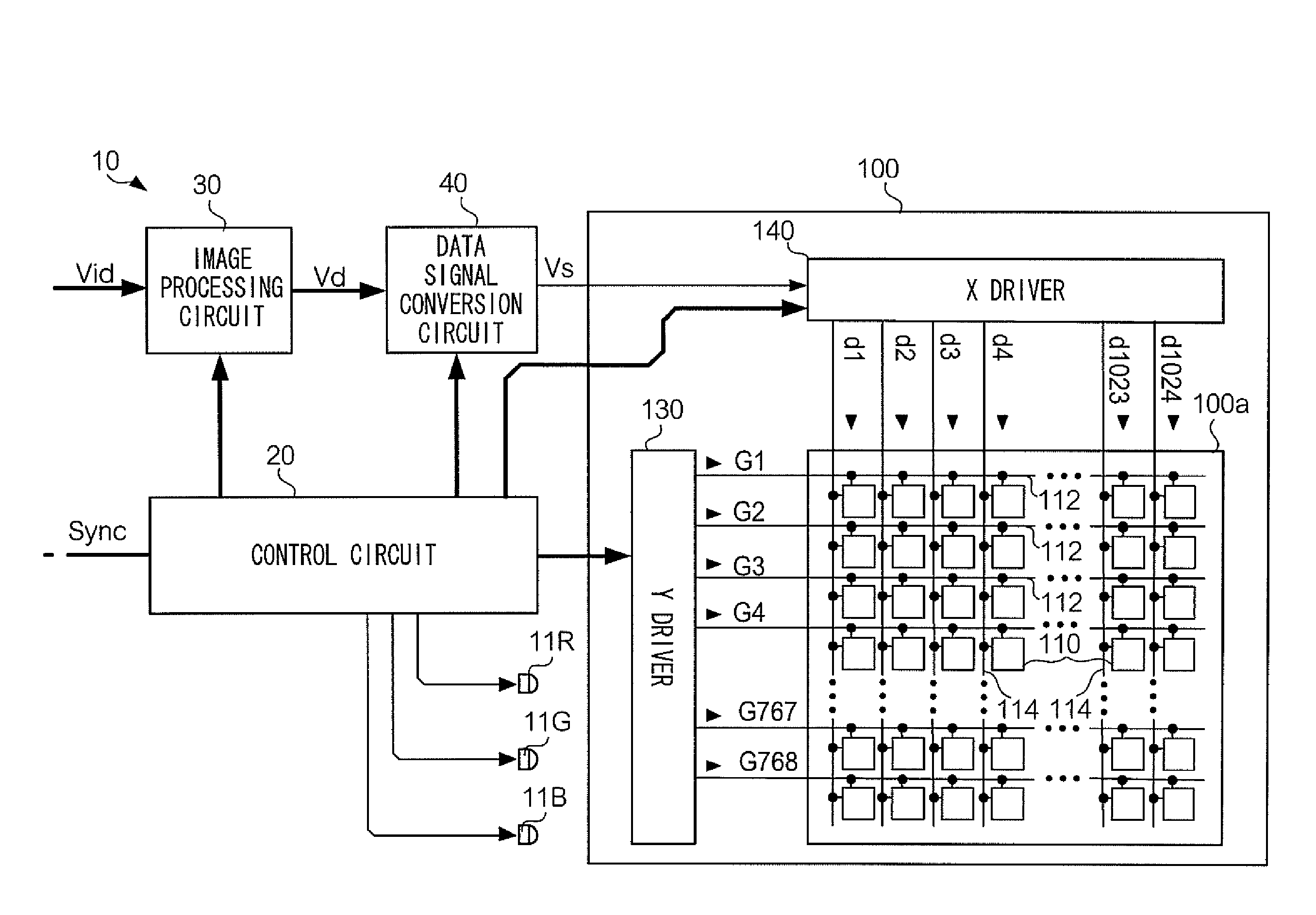
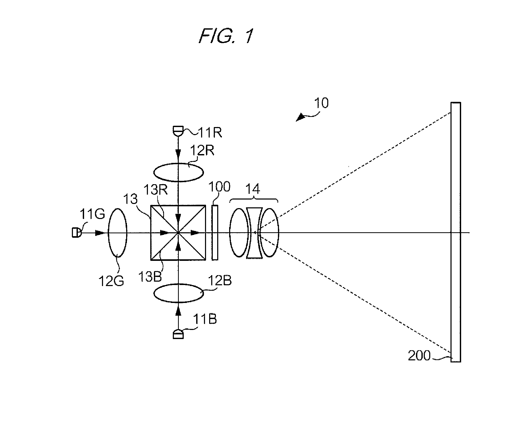
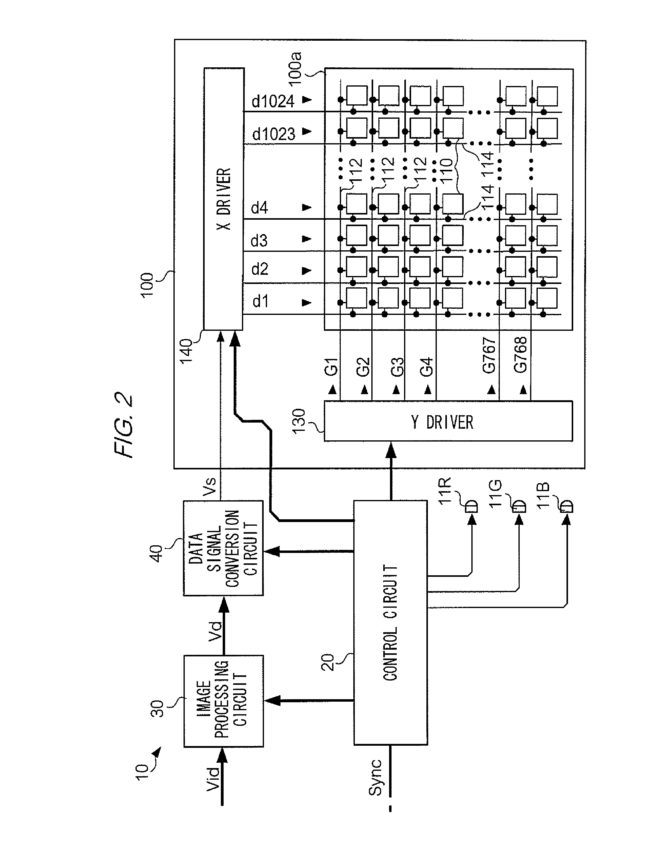
[0037]First, a description is given for a driving method for an electro-optical apparatus according to a first exemplary embodiment of the invention. FIG. 1 shows an optical configuration of a projector 10 that is an example of an electro-optical apparatus to which this driving method has been applied. In FIG. 1, an LED 11R is located in the direction of 12 o'clock as viewed from the center of a dichroic prism 13. The LED 11R is a light emitting diode that emits R (red) light downward in FIG. 1. The R light emitted by the LED 11R is focused into a substantially parallel light beam by a collimator lens 12R. Likewise, an LED 11G and an LED 11B are located in directions of 9 o'clock and 6 o'clock respectively. The LED 11G is a light emitting diode that emits G (green) light rightward in FIG. 1, and the LED 11B is a light emitting diode that emits B (blue) light upward in FIG. 1. The G and B light emitted by the LEDs 11G and 11B are also focused into substan...
second exemplary embodiment
2. Second Exemplary Embodiment
[0055]In the color sequential driving according to the first exemplary embodiment, the R, G, and B wait periods are set in consideration of the fact that optical responsiveness depends on the wavelength. According to this configuration, it is possible to avoid a situation in which a different brightness from the brightness designated by the video signal Vid is viewed, but there are cases in which it is difficult to increase the brightness of the entire screen since the R, G and B light emission periods cannot be long. In view of this, in a second exemplary embodiment, emphasis is placed on increasing the brightness of the screen.
[0056]FIG. 7 shows color sequential driving according to the second exemplary embodiment. In the second exemplary embodiment, the writing method in the R scan period (R first scan period) is changed, and furthermore, an R second scan period is added. Likewise, the writing in the G scan period (G first scan period) is changed, an...
third exemplary embodiment
3. Third Exemplary Embodiment
[0068]The color sequential driving according to the second exemplary embodiment is effective in terms of ensuring screen brightness, but for the G component whose visibility is the highest, the G light emission period starts during the G second vertical scan, and therefore there is room for improvement in terms of the resolution that is actually viewed. In a third exemplary embodiment, emphasis is placed on an improvement in resolution.
[0069]FIG. 10 shows color sequential driving according to the third exemplary embodiment. In the third exemplary embodiment, the R second scan period of the second exemplary embodiment is omitted, and furthermore, the G sub-frame period includes a G scan period that does not cause a reduction in resolution similarly to the first exemplary embodiment. Specifically, two scan lines are simultaneously selected in the R and B first scan periods, but the scan lines are selected one-by-one in the G scan period. Also, in the third...
PUM
 Abstract
Description
Claims
Application Information
 - R&D
- Intellectual Property
- Life Sciences
- Materials
- Tech Scout
- Unparalleled Data Quality
- Higher Quality Content
- 60% Fewer Hallucinations
Browse by: Latest US Patents, China's latest patents, Technical Efficacy Thesaurus, Application Domain, Technology Topic, Popular Technical Reports.
© 2025 PatSnap. All rights reserved.Legal|Privacy policy|Modern Slavery Act Transparency Statement|Sitemap|About US| Contact US: help@patsnap.com