Transflective liquid crystal display

a liquid crystal display and transmission type technology, applied in non-linear optics, instruments, optics, etc., can solve the problems of high power consumption, display light cannot be easily observed, and liquid crystal displays of transmission type consume a large amount of power to keep the backlight, so as to enhance the utilization ratio of light beams, improve the effect of optical response and different thickness

Inactive Publication Date: 2005-10-20
INNOLUX CORP
View PDF2 Cites 1 Cited by
  • Summary
  • Abstract
  • Description
  • Claims
  • Application Information

AI Technical Summary

Benefits of technology

[0017] The LCD has different thickness in the reflection display region and transmission region, i.e. double cell gap, which can utilize the optical characterization of transmission and reflection at the same time to enhance the utilization ratio of light beams, corresponding to the LCD with a single cell gap. Furthermore, the LCD has a hybrid-bend liquid crystal profile, that is the orientation of the liquid crystal of the present LCD is substantially different, in the reflection display region and the transmission display region. Therefore, the LCD possesses fast optical response for true video rate, such as for TV applications, motion pictures, fast electro optical devices. By using the large tilt angle of the reflection region and the small tilt angle of the transmission region and the continuous elastic deformation between the liquid crystal molecular, the LCD overcomes the long splay-to-bend state transition time and unstable state.

Problems solved by technology

However, since these types of displays emit display light and use the same directly for the display, they have high power consumption.
Therefore if the display is used under circumstances where ambient light is brighter than the luminance (for example, in direct sunlight), then a phenomenon known as “wash-out” invariably occurs, and the display light cannot be easily observed.
On the other hand, liquid crystal displays of the transmission type consume a large amount of power to keep the backlight on.
Thus, even though only a small amount of power is consumed to adjust transmittance of the liquid crystals, a relatively large amount of power is consumed overall.
Nevertheless, it becomes too difficult to readily observe the display light on color liquid crystal displays of the transmission type when they are used under the circumstances where the ambient light is very strong and the display light is relatively weak.
This problem can be eliminated by using a brighter backlight, but this solution further increases power consumption.
When the ambient light is weak, the display content cannot be easily observed.
Thus, when used under these circumstances, the ambient light problem is even more pronounced.
However, the optical properties are not good for transmissive and reflective optical properties.
Another drawback of slow response causes TN and MTN LCD cannot be used for moving pictures.
However the bend state is not stable at low voltage.
It takes a long warm-up time before working the LCD and there are domains emerge between pixels to damage the image quality.

Method used


Image

  • Transflective liquid crystal display
  • Transflective liquid crystal display
  • Transflective liquid crystal display

Examples


Embodiment Construction

[0022] Hereinafter, preferred embodiments of the present invention will be explained in detail with reference to the accompanying drawings.

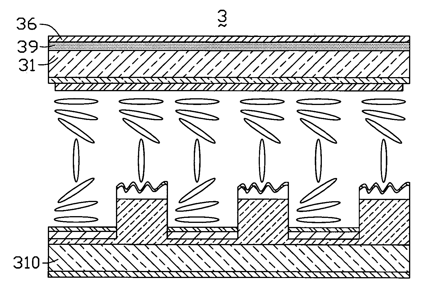
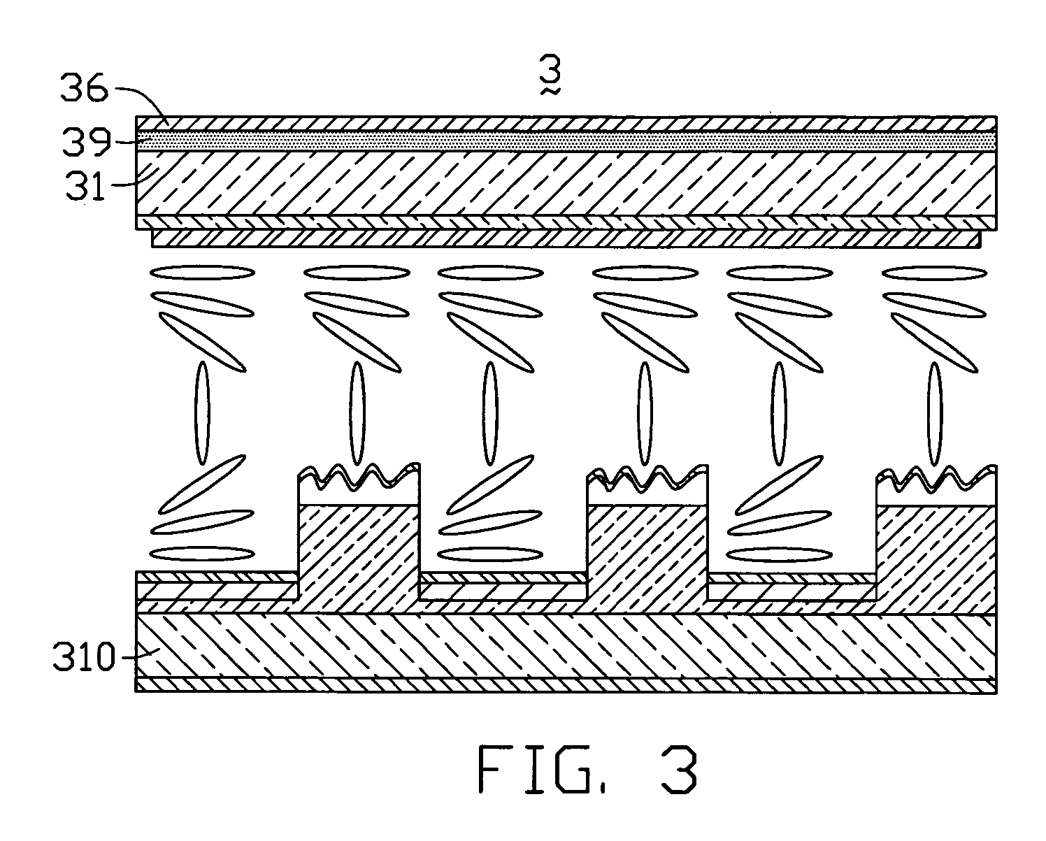
[0023]FIG. 1 shows a cross-section of a portion of a transflective LCD 2 according to the first embodiment of the present invention. The transflective LCD 2 includes a first electrode substrate 100, a second electrode substrate 200 opposite to the first electrode substrate 100, and a liquid crystal layer 20 sandwiched between the first electrode substrate 100 and the second electrode substrate 200. The first electrode substrate 100 includes an alignment film 231, which contacts the liquid crystal layer 20. That is, the alignment film 231 serves as an interface between the first electrode substrate 100 and the liquid crystal layer 20. Rubbing treatment has been applied to the alignment film 231, so that the alignment film 231 provides a tilt angle of less than 10 degrees. The second electrode substrate 200 includes an alignment film 23, which con...


PUM

PropertyMeasurementUnit
tilt anglesaaaaaaaaaa

Abstract

A transflective liquid crystal display (2) has a first substrate (21), a second substrate (210) opposite to the first substrate, an alignment means (23, 231) provided on respective opposing surface of the first and second substrates, and a liquid crystal layer (20) sandwiched between the first and second substrates. The liquid crystal molecules of the liquid crystal layer have two different orientations respectively corresponding to a transmission display region (20a) and a reflection display region (20b). Furthermore, the transflective liquid crystal display has two different thicknesses respectively corresponding to the reflection region and the transmission region.

Description

BACKGROUND OF THE INVENTION [0001] 1. Field of the Invention [0002] The present invention relates to a transflective liquid crystal display (LCD), and particularly to a transflective LCD with a so-called hybrid bend. [0003] 2. General Background [0004] Typically, Cathode Ray Tubes (CRT), Electroluminescence (EL) elements, Plasma Display Panels (PDPs) etc. have been put into practical use as displays of the light emissive type in which display contents can be overwritten electrically. [0005] However, since these types of displays emit display light and use the same directly for the display, they have high power consumption. Further, the light-emitting surface of these types of display serves as a display surface having high reflectance. Therefore if the display is used under circumstances where ambient light is brighter than the luminance (for example, in direct sunlight), then a phenomenon known as “wash-out” invariably occurs, and the display light cannot be easily observed. [0006]...

Claims


Application Information

Patent Timeline
Patent Type & Authority Applications(United States)
IPC IPC(8): G02F1/1333G02F1/1335G02F1/1337
CPCG02F1/133371G02F2001/133761G02F2001/133757G02F1/133555G02F1/133761G02F1/133757
Inventor YANG, CHIU-LIENCHEN, CHUEH-JUPANG, JIA-PANG
Owner INNOLUX CORP
Why Eureka
Try Eureka