Laminated optical member, lighting device, display device, and television device with spacers defined in linear shapes along a plate surface with axes tilted relative to an arrangement direction of pixels
a technology of linear shape and optical member, which is applied in the direction of identification means, lighting and heating apparatus, instruments, etc., can solve the problem of insufficient fringe reducing effect, and achieve the effect of properly exerting optical performan
- Summary
- Abstract
- Description
- Claims
- Application Information
AI Technical Summary
Benefits of technology
Problems solved by technology
Method used
Image

Examples
first embodiment
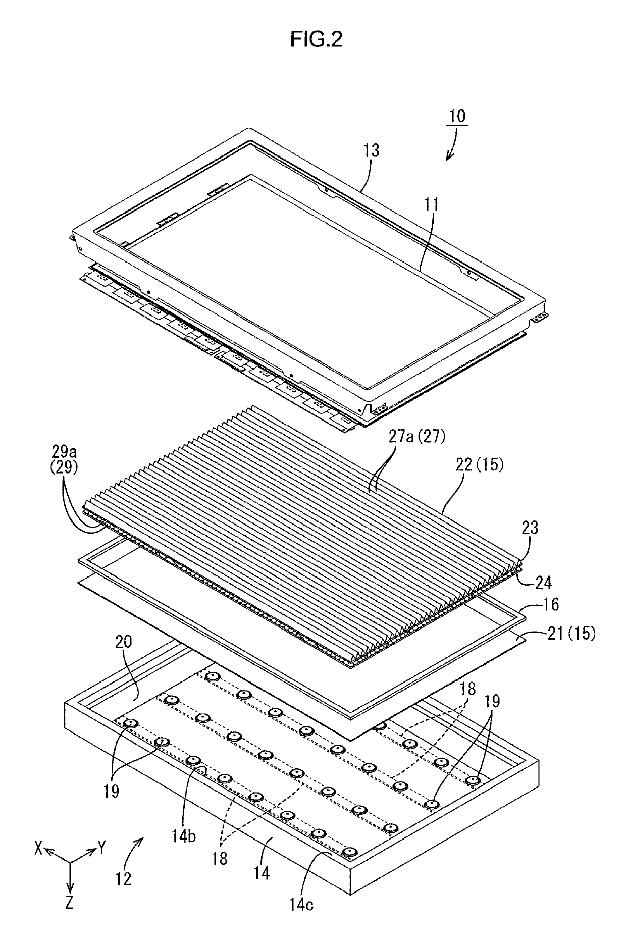
[0048]A first embodiment of the present invention will be described with reference to FIGS. 1 to 10. In this section, a liquid crystal display device 10, a backlight unit 12 used in the liquid crystal display device 10, and a laminated type optical sheet 22 in the backlight unit 12 used in the liquid crystal display device 10 will be described. An X-axis, a Y-axis, and a Z-axis are present in some drawings for the purpose of illustration. The axes in each drawing correspond to the respective axes in other drawings. An upper side and a lower side in FIGS. 4 and 5 correspond to a front side and a rear side of the liquid crystal display device 10, respectively.
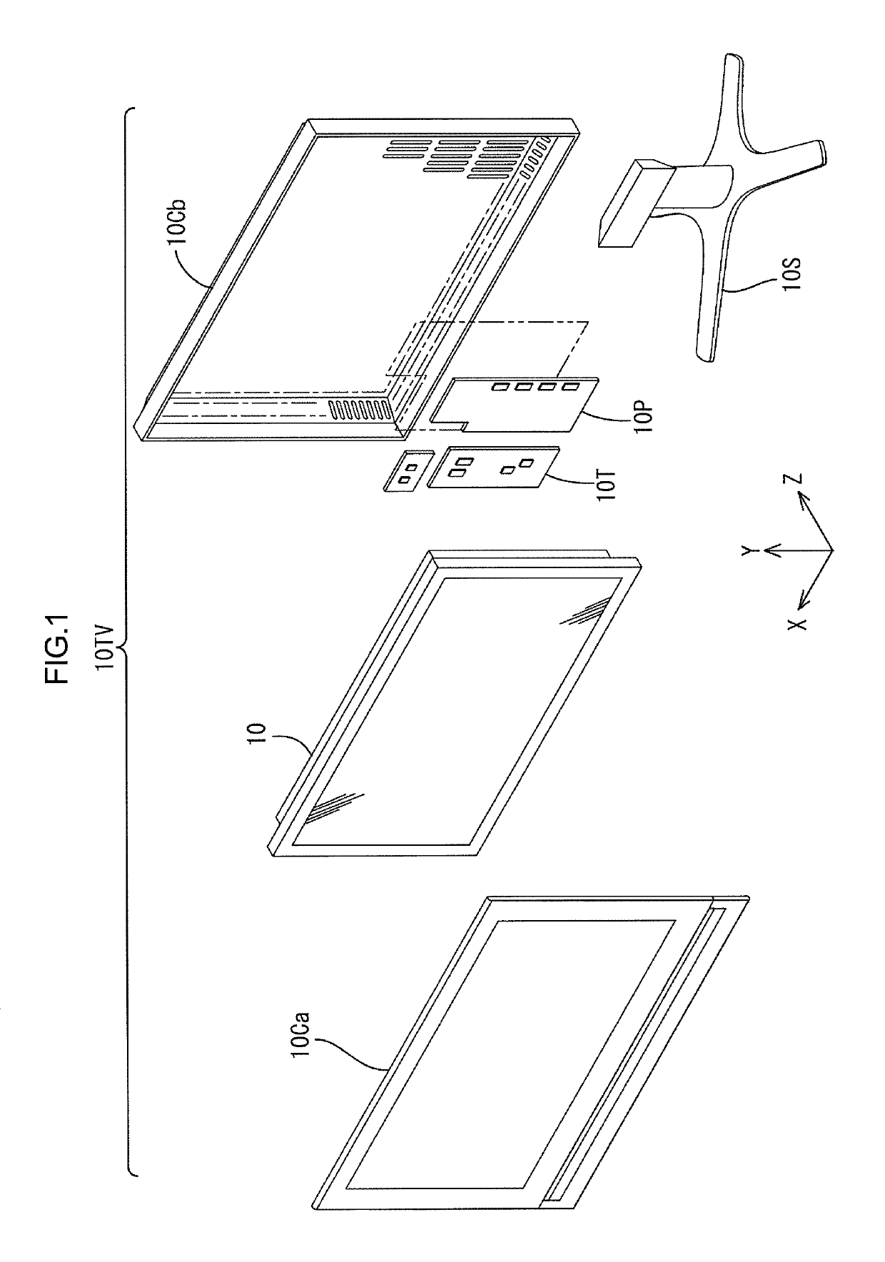
[0049]As illustrated in FIG. 1, a television device 10TV according to this embodiment includes the liquid crystal display device 10, a front cabinet 10Ca, a rear cabinet 10Cb, a power supply 10P, a tuner 10T (a receiver), and a stand 10S. The front cabinet 10Ca and the rear cabinet 10Cb sandwich the liquid crystal display device ...
second embodiment
[0093]A second embodiment of the present invention will be described with reference to FIGS. 11 to 13. The second embodiment includes a laminated type optical sheet 122 having a configuration different from that of the first embodiment. Configurations, functions, and effects similar to those of the first embodiment will not be described.
[0094]As illustrated in FIG. 11, the laminated type optical sheet 122 in this embodiment includes a prism sheet 123 and a reflective type polarizing sheet 30 (a third optical member) which is laid on a front side relative to the prism sheet 123. The laminated type optical sheet 122 has a three-layer structure as a whole. The reflective type polarizing sheet 30 includes a reflective type polarizing film 31 and a pair of diffuser films 32 that sandwich the reflective type polarizing film 31 from the front and the rear. The reflective type polarizing film 31 has a multi-layer structure including layers having different refractive indexes and being alter...
third embodiment
[0102]A third embodiment of the present invention will be described with reference to FIG. 14 or 15. The third embodiment includes spacers 225 that have configurations different from those of the first embodiment. Configurations, functions, and effects similar to those of the first embodiment will not be described.
[0103]As illustrated in FIGS. 14 and 15, spacers 225 in this embodiment linearly extend with breaks within a plate surface of a micro lens sheet 224. Namely, multiple linear unit spacers 34 that extend along an axis 225AX are arranged at intervals along the axis 225AX. Each linear unit spacer 34 has a length smaller than a dimension of the micro lens sheet 224 measuring in the X-axis direction (a long dimension). The linear unit spacers 34 arranged at intervals along the same axis 225AX may have lengths different from each other. The linear unit spacers 34 that are adjacent to each other in the Y-axis direction have lengths substantially equal to each other. A distance bet...
PUM
| Property | Measurement | Unit |
|---|---|---|
| angle | aaaaa | aaaaa |
| tilting angle | aaaaa | aaaaa |
| refractive index | aaaaa | aaaaa |
Abstract
Description
Claims
Application Information
 - R&D
- Intellectual Property
- Life Sciences
- Materials
- Tech Scout
- Unparalleled Data Quality
- Higher Quality Content
- 60% Fewer Hallucinations
Browse by: Latest US Patents, China's latest patents, Technical Efficacy Thesaurus, Application Domain, Technology Topic, Popular Technical Reports.
© 2025 PatSnap. All rights reserved.Legal|Privacy policy|Modern Slavery Act Transparency Statement|Sitemap|About US| Contact US: help@patsnap.com