
Optical fiber

a technology of optical fibers and fibers, applied in the field of optical fibers, can solve the problems of easy cause of optical losses, complicated configuration of optical fibers, and increase costs, and achieve the effects of reducing bending losses, avoiding complicated configurations, and reducing the mode field diameter of ligh

Active Publication Date: 2019-04-23
THE FUJIKURA CABLE WORKS LTD
View PDF41 Cites 0 Cited by
  • Summary
  • Abstract
  • Description
  • Claims
  • Application Information

AI Technical Summary

Benefits of technology

The present invention provides an optical fiber that can reduce the decrease in the mode field diameter of light, avoid a complicated configuration, and reduce bending losses. This is achieved by a specific refractive index profile that prevents a decrease in the mode field diameter of light, while also reducing bending losses. The refractive index of the inner cladding part is smaller than the refractive index of the outer cladding part, or equal to it, which simplifies the configuration of the optical fiber and reduces costs. The refractive index of the inner cladding part can be adjusted to further reduce bending losses.

Problems solved by technology

In this case, optical losses are easily caused, when the optical fiber is connected to another optical fiber.
However, since a trench layer has to be provided on the optical fiber described in Patent Literature 2, there is concern that the configuration of the optical fiber is complicated to increase costs.

Method used


Image

  • Optical fiber
  • Optical fiber
  • Optical fiber

Examples


first embodiment

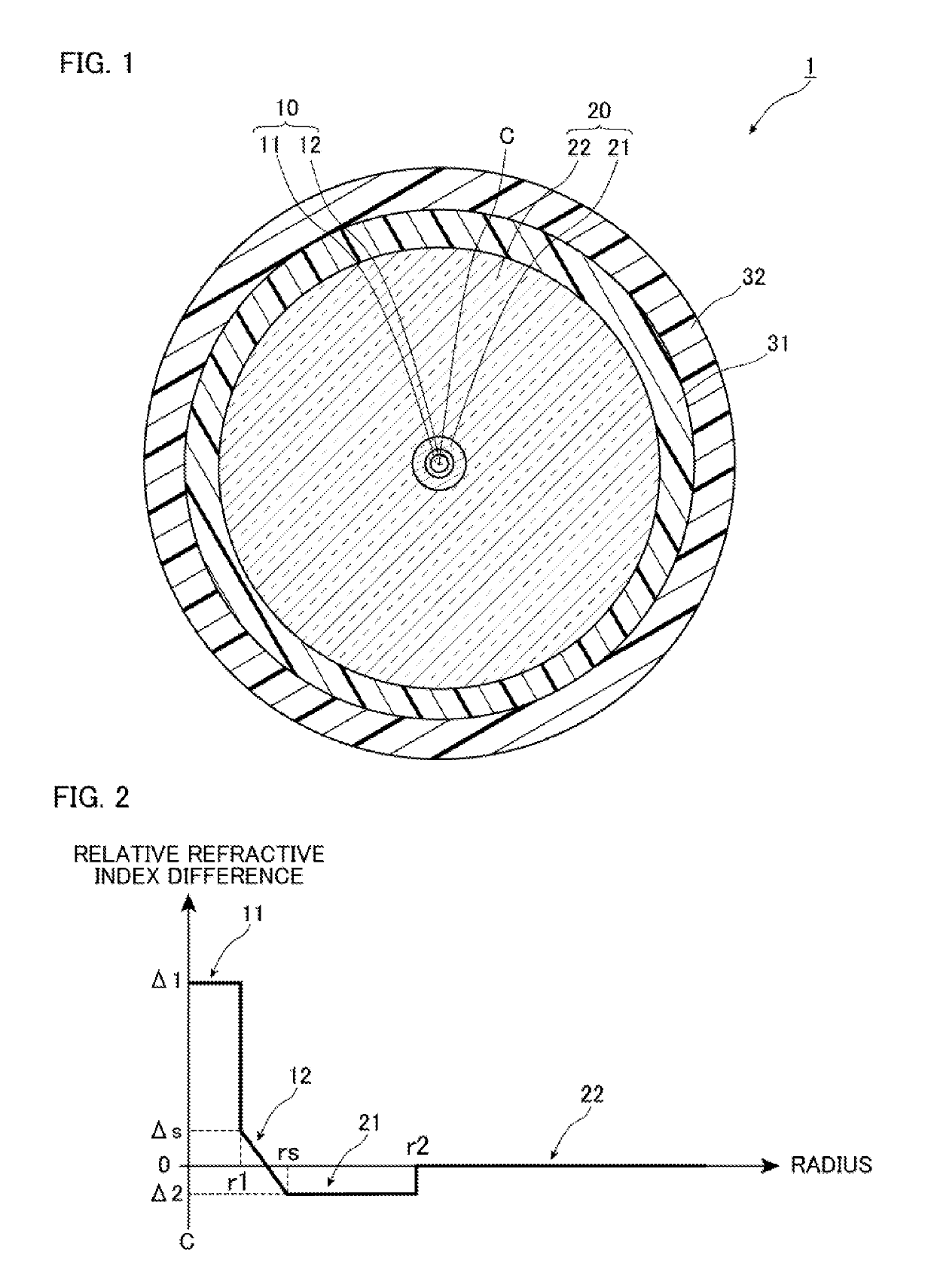
[0034]FIG. 1 is a diagram of the cross sectional structure of an optical fiber according to a first embodiment perpendicular to the longitudinal direction.

[0035]As illustrated in FIG. 1, an optical fiber 1 according to the embodiment includes a core 10, a cladding 20 surrounding the outer circumferential surface of the core 10 with no gap, an inner protective layer 31 covering the outer circumferential surface of the cladding 20, and an outer protective layer 32 covering the outer circumferential surface of the inner protective layer.

[0036]The core 10 is formed of an inner core part 11 including a center axis C of the core 10 and an outer core part 12 surrounding the outer circumferential surface of the inner core part 11 with no gap. The cladding 20 is formed of an inner cladding part 21 surrounding the outer core part 12 of the core 10 with no gap and an outer cladding part 22 surrounding the inner cladding part 21 with no gap.

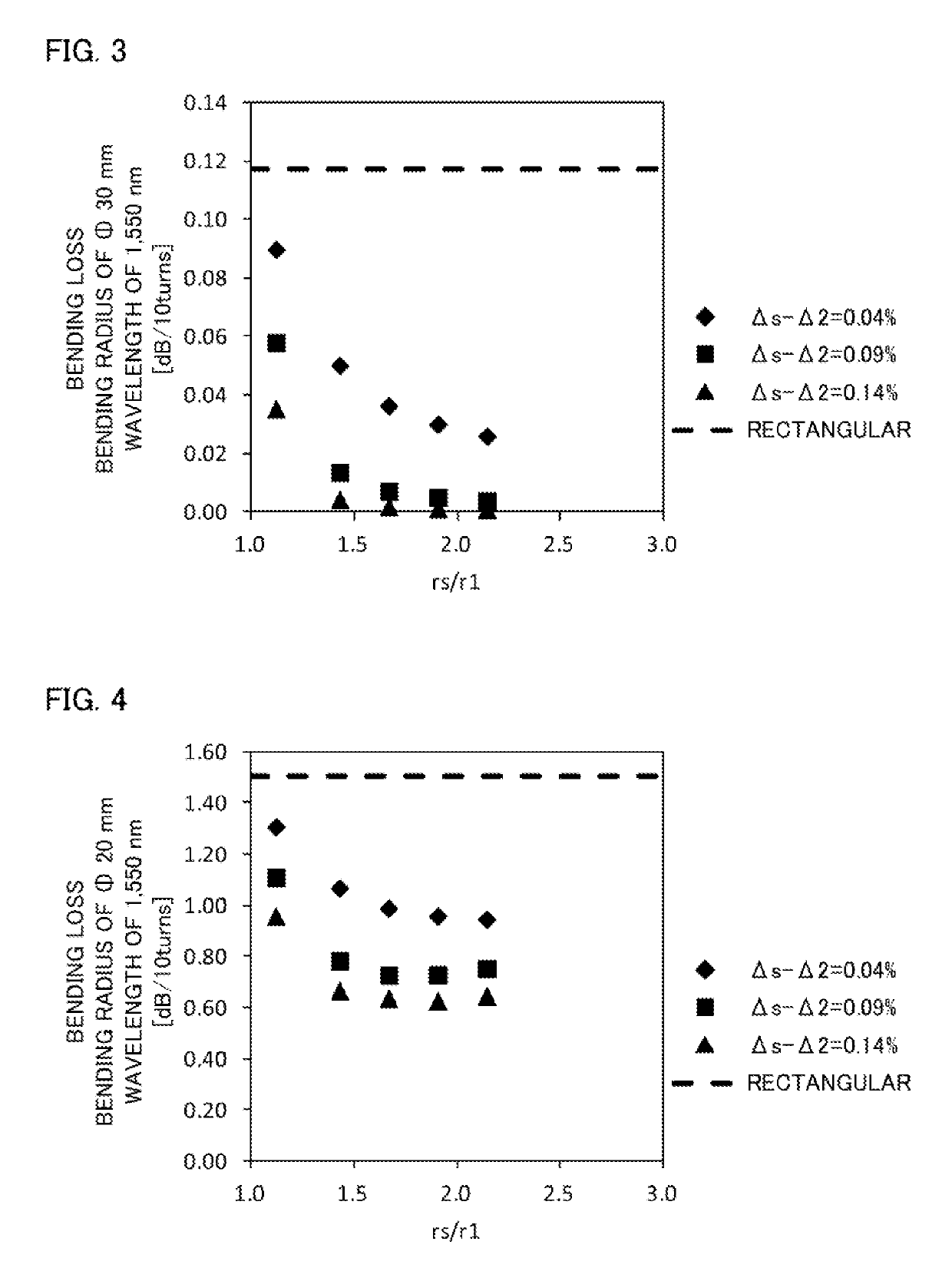
[0037]FIG. 2 is a diagram of the refractive index prof...

second embodiment

[0050]Next, a second embodiment of the optical fiber according to the present invention will be described in detail with reference to FIGS. 10 to 17. Note that, components same as or equivalent to ones of the optical fiber 1 of the first embodiment are designated the same reference numerals and signs, and the overlapping description is omitted, unless otherwise specified.

[0051]FIG. 10 is a diagram of the refractive index profiles of a core 10 and a cladding 20 of an optical fiber according to the embodiment similarly to FIG. 2. As illustrated in FIG. 10, the optical fiber according to the second embodiment is different from the optical fiber 1 according to the first embodiment in that the refractive index of an inner cladding part 21 is equal to the refractive index of an outer cladding part 22.

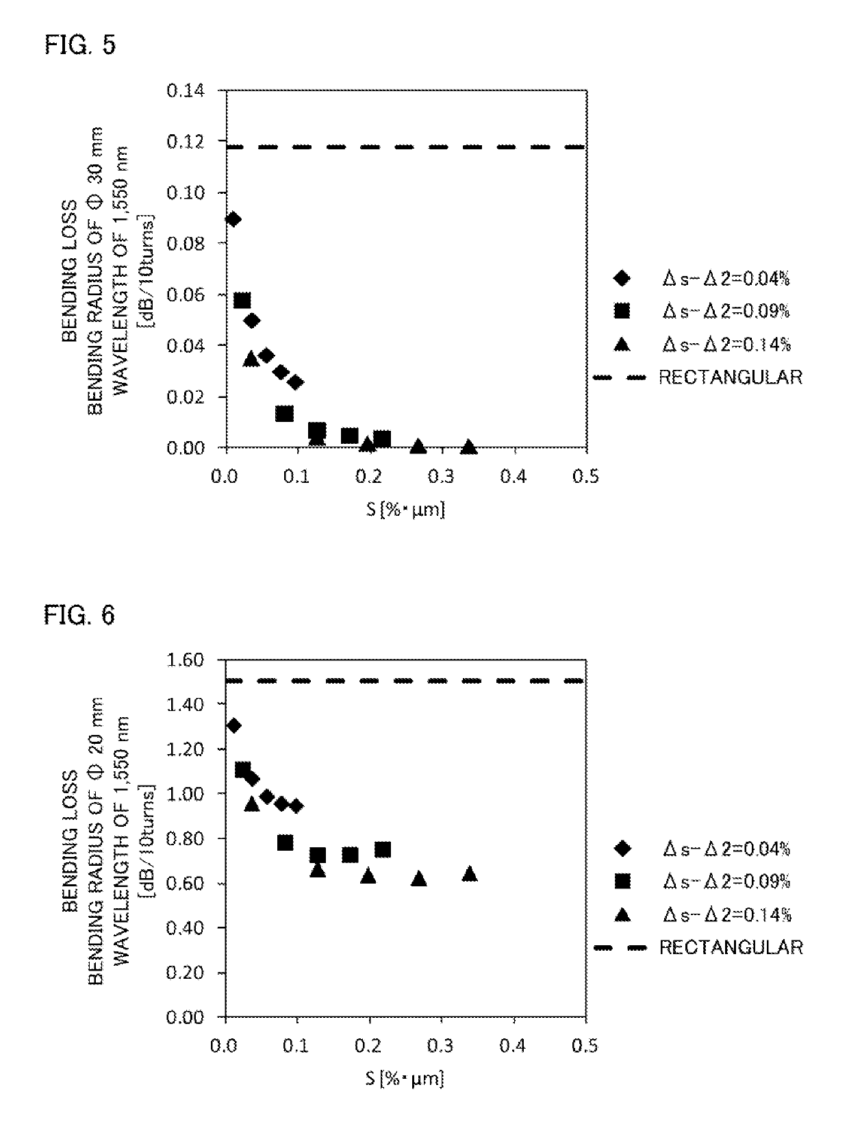
[0052]Here, in the optical fiber according to the embodiment, simulation below is performed. In this simulation, the relative refractive index difference Δ1 of an inner core part 11 was 0.34%...


PUM


Abstract

The refractive index of the inner core part 11 in a region in contact with the boundary of the outer core part 12 is higher than the refractive index of the outer core part 12. The refractive index of the outer core part 12 is gradually decreased from the inner circumferential side to the outer circumferential side. The refractive index of the inner cladding part 21 is equal to the refractive index of the outermost circumferential part of the outer core part 12 and not greater than the refractive index of the outer cladding part 22.

Description

TECHNICAL FIELD[0001]The present invention relates to an optical fiber, which is preferred in the case of reducing bending losses.BACKGROUND ART[0002]Optical fibers used for optical communications are installed in offices, homes, and the like, or are used in optical fiber cables, in which a plurality of optical fibers is disposed in a sheath. In the case in which optical fibers are installed as described above, the optical fibers are typically disposed with at least a part of them being bent. In the case in which optical fibers are used in optical fiber cables as described above, the optical fibers are disposed being bent in the overall structure, because the optical fibers are typically spirally disposed in the sheath.[0003]It is known that when light is propagated through a core of a bent optical fiber, a so-called bending loss occurs, in which light is leaked from the core to cause optical losses. As one example of optical fibers that reduce such bending losses, an optical fiber ...

Claims


Application Information

Patent Timeline
Patent Type & Authority Patents(United States)
IPC IPC(8): G02B6/36G02B6/036G02B6/02G02B6/028
CPCG02B6/036G02B6/0283G02B6/0285G02B6/02395G02B6/0365G02B6/03627
Inventor ENDO, SHOKITAMURA, TAKAYUKI
Owner THE FUJIKURA CABLE WORKS LTD
Learn More