Electric power steering system
- Summary
- Abstract
- Description
- Claims
- Application Information
AI Technical Summary
Benefits of technology
Problems solved by technology
Method used
Image
Examples
Embodiment Construction
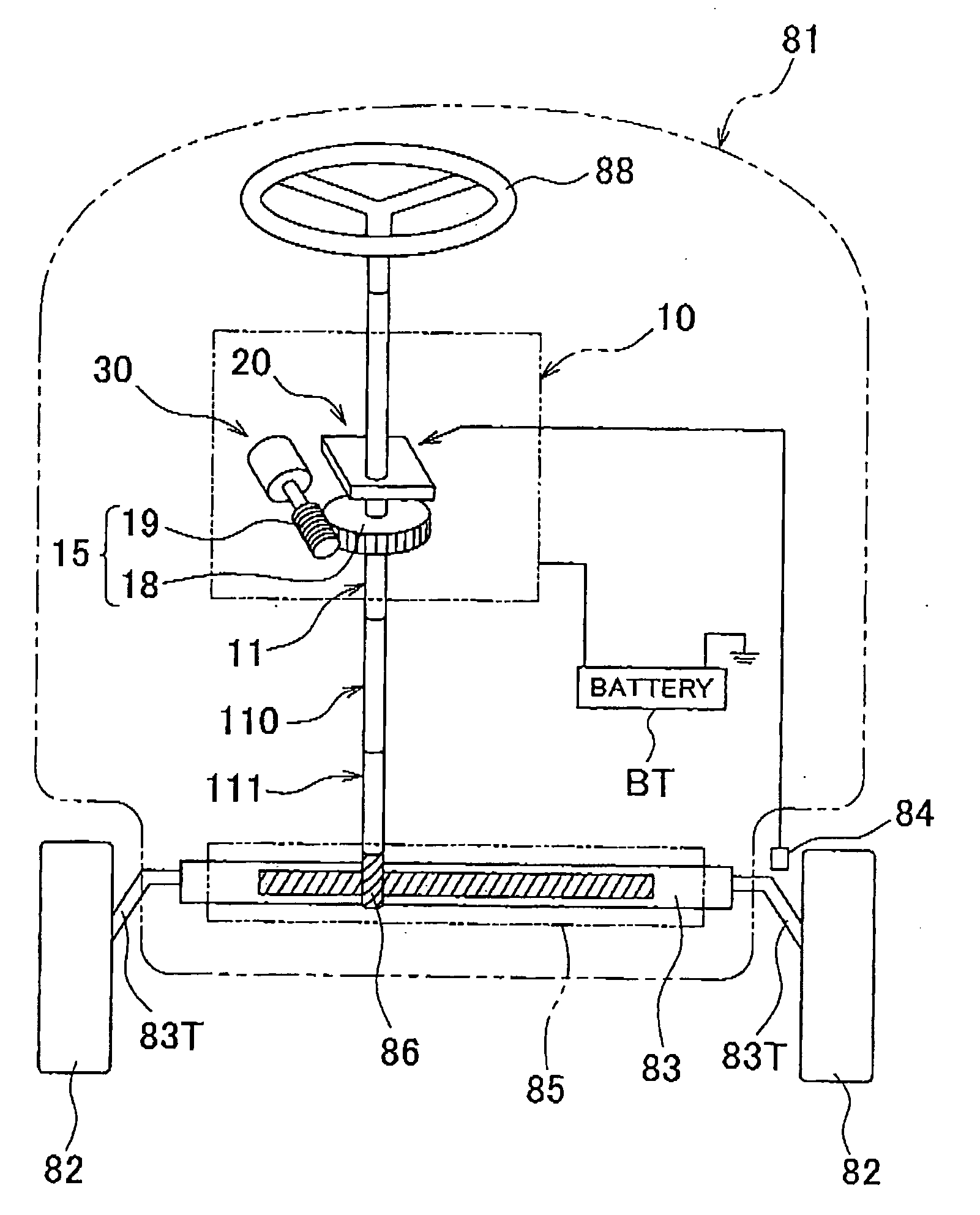
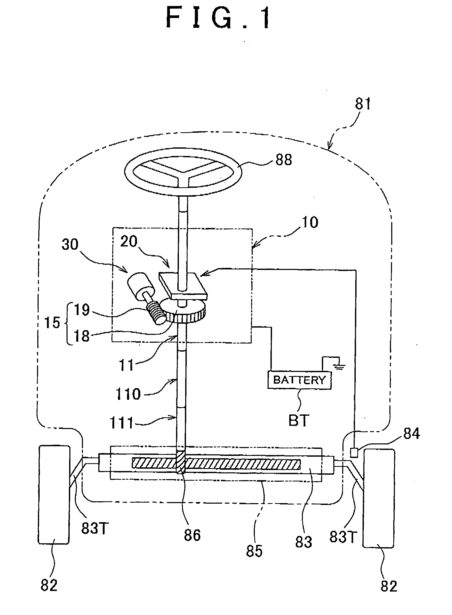
[0022]An embodiment of the invention will be described below with reference to FIGS. 1 to 11. FIG. 1 shows a vehicle 81, on which an electric power steering system 10 is mounted. A rack 83 is placed between a pair of steered wheels 82 of the vehicle 81 and is inserted into a cylindrical rack case 85. Each end of the rack 83 is connected to the steered wheel 82 through a tie rod 83T. The rack case 83 is fixed to a body of the vehicle 81. A vehicle speed sensor 84 for detecting a vehicle speed based on the rotation of the steered wheel 82 is provided near the steered wheel 82.
[0023]A pinion 86 laterally passing through a middle portion of a rack case 85 meshes with the rack 83. Between the pinion 86 and a steering wheel 88, a plurality of steering shafts 11, 110, and 111 are aligned and connected one after another via universal joints (not shown). The steering shafts 11, 110, and 111 transmit the rotation of the steering wheel 88 to the pinion 86.
[0024]As shown in FIG. 1, the electric...
PUM
 Abstract
Description
Claims
Application Information
 - R&D
- Intellectual Property
- Life Sciences
- Materials
- Tech Scout
- Unparalleled Data Quality
- Higher Quality Content
- 60% Fewer Hallucinations
Browse by: Latest US Patents, China's latest patents, Technical Efficacy Thesaurus, Application Domain, Technology Topic, Popular Technical Reports.
© 2025 PatSnap. All rights reserved.Legal|Privacy policy|Modern Slavery Act Transparency Statement|Sitemap|About US| Contact US: help@patsnap.com


