
Steering device

Active Publication Date: 2019-07-04
KYB CORP
View PDF0 Cites 0 Cited by
  • Summary
  • Abstract
  • Description
  • Claims
  • Application Information

AI Technical Summary

Benefits of technology

The invention is about a steering system that is easy to install in a vehicle. The technical effect of the patent text is to provide a better mounting mechanism for a steering system in a vehicle.

Problems solved by technology

Thus, there is a problem of poor workability in mounting the steering device on the vehicle body.
For example, if the rack tube has to be passed through an opening provided in a vehicle body frame, the mount bracket portions cannot be inserted into the opening depending on the size of the opening and it may not be possible to mount the steering device.

Method used


Image

  • Steering device
  • Steering device
  • Steering device

Examples


modification 1-1

[0084]For example, as shown in FIG. 9A, small bolt mounting portions 221 may project in the front-rear direction from a lower end part of the rack housing 151.

modification 1-2

[0085]As shown in FIG. 9B, first and second small bolt mounting portions 321A, 321B may be arranged so as to be shifted in the vertical direction.

[0086]As shown in FIGS. 9A and 9B, in Modifications 1, the first small bolt mounting portion 221A, 321A serving as the first vehicle body mounting portion and the second small bolt mounting portion 221B, 321B serving as the second vehicle body mounting portion project in directions opposite to each other as in the above embodiment. Thus, also in Modifications 1, the position adjustment of the steering device 100 can be completed if the steering device 100 is moved to the front side of the vehicle body when the second small bolt mounting portion 221B, 321B is inserted through the opening 91 as in the above embodiment, wherefore workability is better than in Modification 2 to be described below.

modification 2

[0087]Although an example in which the first and second small bolt mounting portions 121A, 121B project in the directions opposite to each other has been described in the above embodiment, the present invention is not limited to this. As shown in FIG. 10, a first small bolt mounting portion 421A serving as the first vehicle body mounting portion may be caused to project upwardly of the vehicle body and a second small bolt mounting portion 421B serving as the second vehicle body mounting portion may be caused to project rearwardly of the vehicle body. In this case, as shown in FIG. 10, the steering device 100 is rotated by 90° with the center axis O as a center of rotation so that the second small bolt mounting portion 421B faces upward after the first small bolt mounting portion 421A is inserted through the opening 91. Thereafter, the second small bolt mounting portion 421B is inserted into the opening 91.


PUM


Abstract

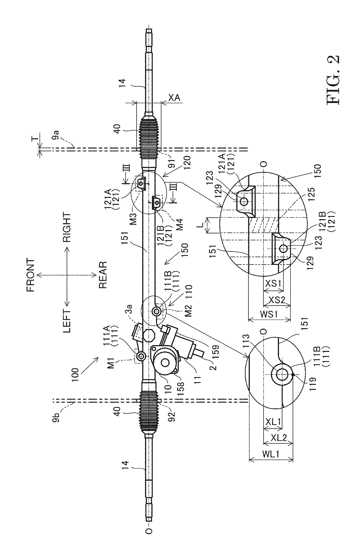
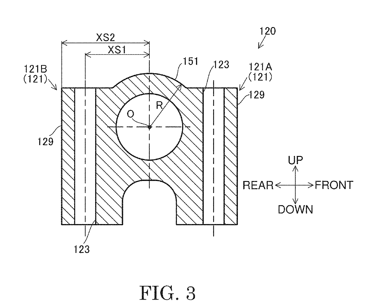
A steering device includes a rack housing portion housing a rack shaft, a pinion gear provided on one end side of the rack housing portion, a first supporting portion provided on the rack housing portion to support the one end side of the rack housing portion, and a second supporting portion provided on the rack housing portion to support the other end side of the rack housing portion. The second supporting portion includes a first vehicle body mounting portion and a second vehicle body mounting portion provided to project outwardly of the rack housing portion, the first and second vehicle body mounting portions being mounted on a vehicle body. The first and second vehicle body mounting portions are arranged to be shifted in an axial direction of the rack housing portion so as not to overlap in the axial direction.

Description

TECHNICAL FIELD[0001]The present invention relates to a steering device.BACKGROUND ART[0002]JP2013-141969A describes a steering device provided in an engine compartment of a vehicle to apply a steering assist force to a turning wheel. In this steering device, mount bracket portions for mounting a rack tube on the side of a vehicle body are provided on both ends of the rack tube.SUMMARY OF INVENTION[0003]However, since a pair of the mount bracket portions are provided at positions symmetrical with respect to a center axis of the rack tube in the steering device described in JP2013-141969A, a part where the mount bracket portions are provided has a large width (external dimension in a direction perpendicular to the center axis of the rack tube). Thus, there is a problem of poor workability in mounting the steering device on the vehicle body. For example, if the rack tube has to be passed through an opening provided in a vehicle body frame, the mount bracket portions cannot be inserted...

Claims


Application Information

Patent Timeline
IPC IPC(8): B62D3/12F16H55/26B62D5/04
CPCB62D3/126F16H55/26B62D5/0409B62D3/12B62D5/0421
Inventor MIYAKE, SOICHIROTSUKADA, YOSHIYUKI
Owner KYB CORP
Learn More