Solid-state battery
a solid-state battery and battery technology, applied in the field of solid-state batteries, can solve the problems of connection failure between solid-state batteries and substrates, new problem of inferior mountability,
- Summary
- Abstract
- Description
- Claims
- Application Information
AI Technical Summary
Benefits of technology
Problems solved by technology
Method used
Image
Examples
first embodiment
[0044]The solid-state battery of the present embodiment includes a solid-state battery main portion, an end surface electrode, and a lower surface electrode.
[0045](Solid-State Battery Main Portion)
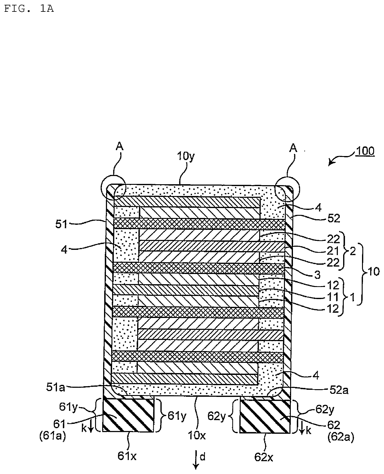
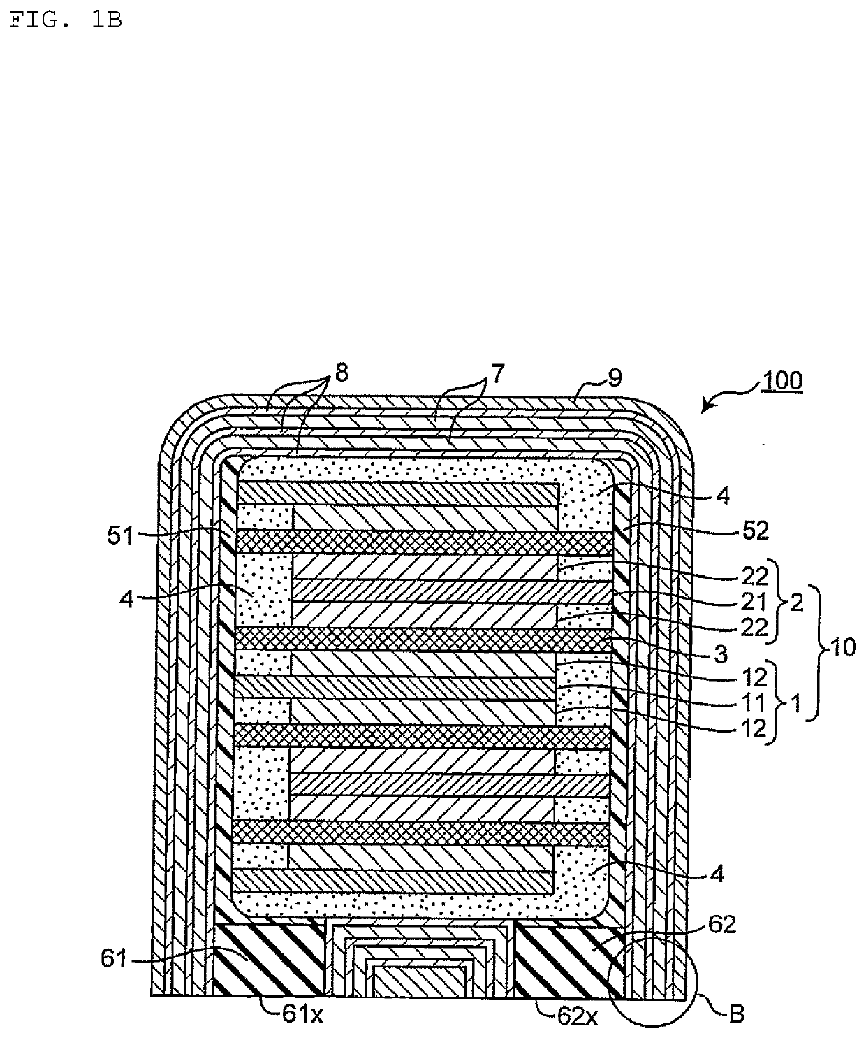
[0046]The solid-state battery main portion has a chip shape, and includes a positive electrode layer and a negative electrode layer as internal electrodes. The solid-state battery main portion usually further includes a solid electrolyte layer. Specifically, as illustrated in FIG. 1A, the solid-state battery 100 includes a solid-state battery main portion 10 in which a negative electrode layer 1 and a positive electrode layer 2 are alternately stacked with a solid electrolyte layer 3 interposed therebetween. The chip shape is a so-called rectangular parallelepiped shape or a hexahedron shape including a cube. FIG. 1A is a sectional view schematically illustrating a structure of a solid-state battery according to the first embodiment of the present invention.
[0047]In the solid-state battery...
second embodiment
[0137]The solid-state battery of the present embodiment is the same as the solid-state battery of the first embodiment except that it has the following features.
[0138]As illustrated in FIGS. 2A, 2B, and 2C, the lower surface electrodes 61 and 62 are provided by lead frames 65 and 66. FIG. 2A is a schematic view (top view) of a lead frame sheet including a plurality of lead frames that provide the lower surface electrode. FIG. 2B is a bottom view of a solid-state battery according to a second embodiment of the present invention using the lead frame as the lower surface electrode. FIG. 2C is a front view of the solid-state battery of FIG. 2B.
[0139]Lead frames 65 and 66 are electrode members manufactured in advance, and are provided by a lead frame sheet 600. The lead frame sheet 600 includes one or more sets of lead frames 65 and 66, a frame for lead frame 67 that holds the lead frame, and a connection portion (wire portion) 68 that fixes the frame and the lead frame. The lead frames ...
third embodiment
[0146]The solid-state battery of the present embodiment is the same as the solid-state battery of the first embodiment except that it has the following features.
[0147]As illustrated in FIGS. 3A, 3B, 3C, and 3D, the lower surface electrodes 61′ and 62′ have not only lower surface portions 61a and 62a having a plate shape disposed on the lower surface 10x side of the solid-state battery main portion 10 in a sectional view, but also extending portions 61b and 62b electrically connected to the lower surface portions 61a and 62a and extending on the surfaces of the end surface electrodes 51 and 52. The lower surface electrodes 61′ and 62′ having such a sectional view shape may also be referred to as “L-shaped lower surface electrodes”. FIG. 3A is a sectional view schematically illustrating a structure of a solid-state battery according to the third embodiment of the present invention. FIG. 3B is a sectional view schematically illustrating a structure of the solid-state battery in a case ...
PUM
 Abstract
Description
Claims
Application Information
 - R&D
- Intellectual Property
- Life Sciences
- Materials
- Tech Scout
- Unparalleled Data Quality
- Higher Quality Content
- 60% Fewer Hallucinations
Browse by: Latest US Patents, China's latest patents, Technical Efficacy Thesaurus, Application Domain, Technology Topic, Popular Technical Reports.
© 2025 PatSnap. All rights reserved.Legal|Privacy policy|Modern Slavery Act Transparency Statement|Sitemap|About US| Contact US: help@patsnap.com


