Gamma- ray detector and pet apparatus using the same

a technology of gamma-ray detector and pet apparatus, applied in tomography, instruments, applications, etc., can solve the problems of reducing sensitivity, increasing and enlarge the area, so as to reduce the size of the entire system, shorten the diagnosis time, and suppress the increase in the number of readout channels

Inactive Publication Date: 2010-04-22
HIGH ENERGY ACCELERATOR RESEARCH ORGANIZATION
View PDF3 Cites 8 Cited by
  • Summary
  • Abstract
  • Description
  • Claims
  • Application Information

AI Technical Summary

Benefits of technology

[0012]The present invention was made in view of the above-mentioned circumstances, and it is an object of the invention to provide a gamma-ray detector capable of suppressing increases in the number of readout channels on the ionization electron detection side, facilitating formation of the uniform electric field in the medium, and realizing high-resolution detection of the three-dimensional position, time and energy of the gamma ray in the energy MeV region, and a PET apparatus using the detector.
[0014]According to thus configured gamma-ray detector, since such a structure is provided that a pair of anode pads are disposed at the both end portions in the intersectional direction with respect to the gamma-ray incident direction and that the intermediate electrode is arranged between the anode pads, it is possible to generate the drift electric field for drifting ionization electrons to the left or right directions of the intermediate electrode, and it is possible to reduce the anode area greatly as compared with the case that the anode pads are provided on the entire main plane even in the case of forming a full-scale PET apparatus such that the medium area surrounds the entire outer regions of a test body. Further, since the intermediate electrode is disposed at midpoint of right and left sided anode pads, it is possible to reduce the drift distance of the ionization electrons in spite of an unsplit medium, and to achieve high position resolution. Furthermore, the voltage applied to the intermediate electrode to generate the drift electric field is only an half the conventional voltage with respect to the entire length in the body axis that is the drift direction, and increasing the length in the body axis is also made ease.
[0021]According to thus configured gamma-ray detector, by verifying agreement between the first position information (xPMT, yPMT, zPMT) calculated from the output signals of the photomultiplier tubes and the second position information (xTPC, yTPC, zTPC) calculated from the output signals of the anode pads and gamma-ray reaction time t0 obtained from the output signals of the photomultiplier tubes, it is possible to eliminate the background, and achieve high detection precision.
[0027]According to thus configured PET apparatus, since coincidence of gamma-ray emission directions is judged to determine two gamma rays emitted from the same radioactive isotope, it is possible to distinguish the gamma rays from others emitted from different radioactive isotopes, and improve accuracy in specifying the position of the radioactive isotope.
[0030]According to thus configured nuclear medicine diagnosis system, it is possible to reduce the size of the entire system, while performing PET diagnosis and MRI diagnosis in parallel with each other, and to shorten the diagnosis time.

Problems solved by technology

Further, in modules (cubic), the number of pads increases in the collector pad 110, and the problem arises that the number of readout channels increases.
Further, when it is intended to form a single PET apparatus using a large number of above-mentioned detector modules 100, the clearance occurs between modules, the dead area enlarges, and the problem arises that the sensitivity decreases.
Furthermore, when the detector module 100 is formed in one piece instead of being formed in modules, since the incident direction of the gamma ray 150 is the same as the drift direction of the ionization electron, there is the problem that it is difficult to form a uniform electric field in the detector module 100.

Method used


Image

  • Gamma- ray detector  and pet apparatus using the same
  • Gamma- ray detector  and pet apparatus using the same
  • Gamma- ray detector  and pet apparatus using the same

Examples


Embodiment Construction

[0044]One embodiment of the present invention will specifically be described below with reference to accompanying drawings.

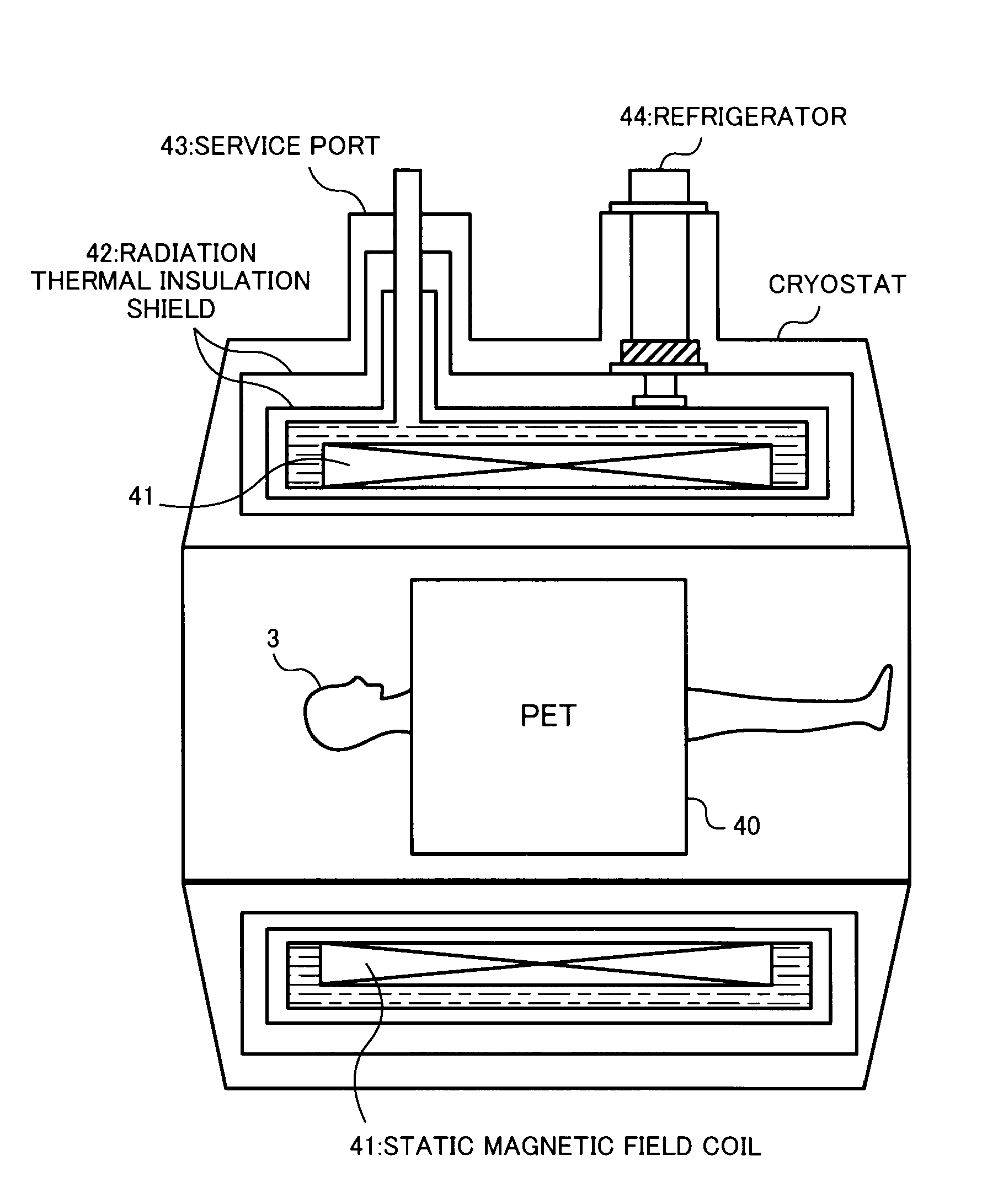
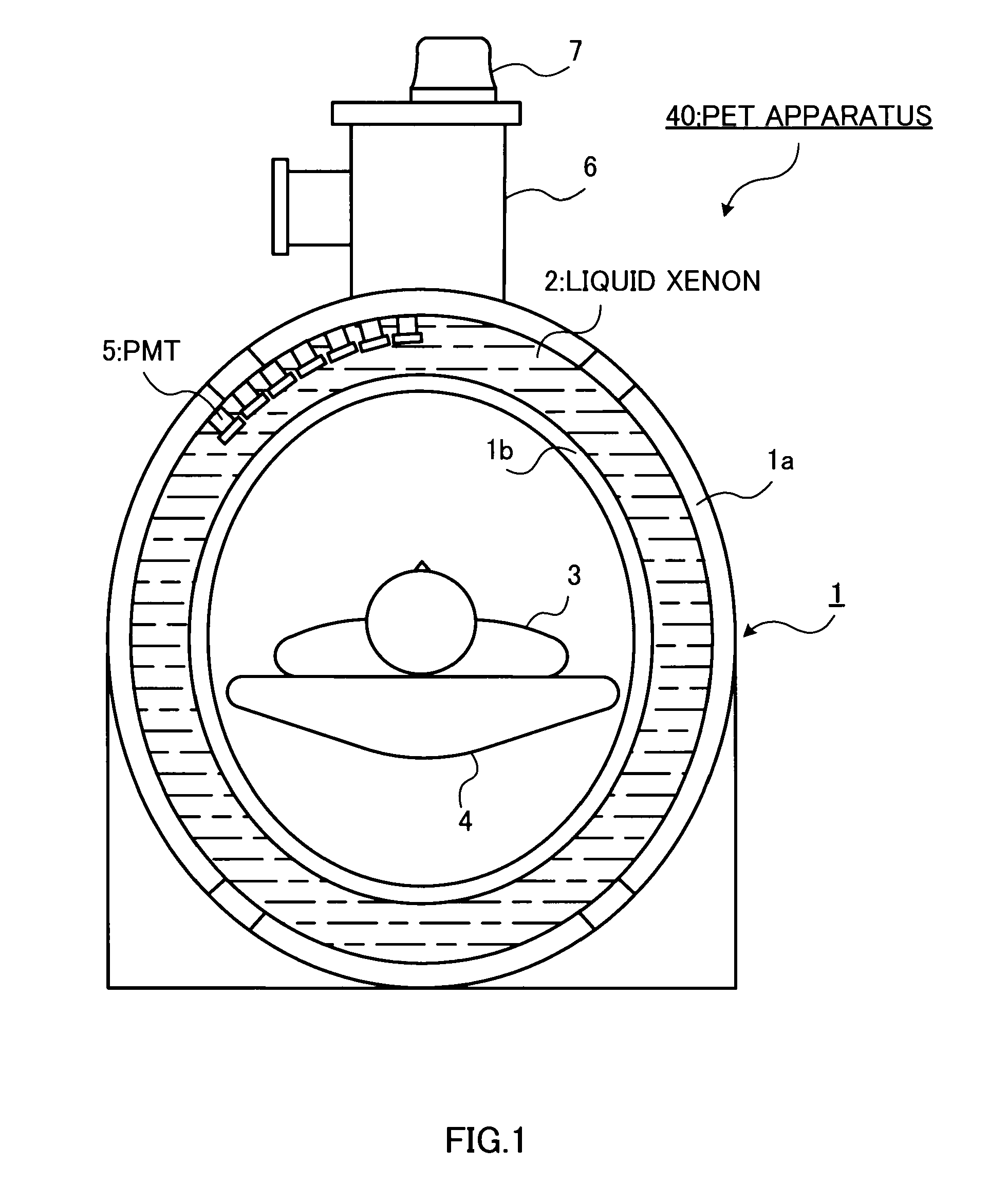
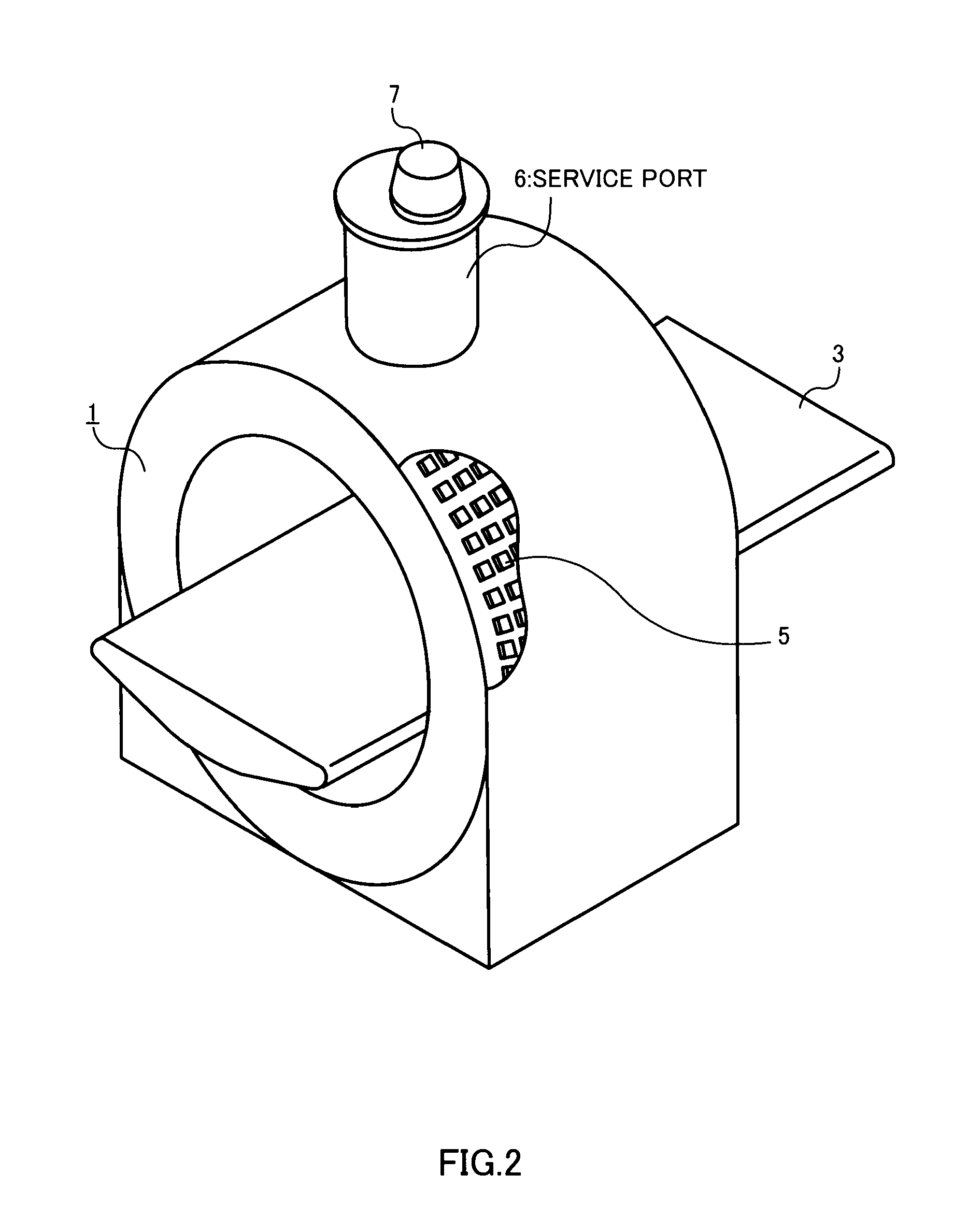
[0045]FIG. 1 is a perpendicular cross-sectional view of a PET apparatus according to one embodiment of the invention, and FIG. 2 is an external view of the PET apparatus according to this embodiment. A liquid xenon TPC detector 1 has an external cylindrical body 1a forming a cylindrical detector external wall, and an internal cylindrical body 1b forming a cylindrical detector internal wall with a diameter smaller than that of the external cylindrical body 1a. Liquid xenon 2 is filled into the cylindrical space formed between the external cylindrical body 1a and internal cylindrical body 1b of the liquid xenon TPC detector 1. The cylindrical space filled with the liquid xenon 2 is referred to as a liquid area S. A bed 4 relatively movable in the body axis direction with a test body 3 mounted thereon is installed in a cylindrical space inside the internal cylindri...


PUM


Abstract

A medium area (S) filled with liquid xenon (2) is formed between an external cylindrical body (1a) and internal cylindrical body (1b), and a pair of anode pads (11, 12) are disposed in two-dimensional form in opposite end portions of the medium area (S) in the intersection direction with respect to the gamma-ray incident direction. An intermediate electrode (10) is disposed between a pair of anode pads (11, 12), and a plurality of photomultiplier tubes (5) is installed in two-dimensional form in the external cylindrical body (1a). Then, the gamma-ray reaction point within the liquid area (S) is identified from signals output from the anode pads (11, 12) and photomultiplier tubes (5).

Description

TECHNICAL FIELD[0001]The present invention relates to a gamma-ray detector for detecting gamma rays from a test body in nuclear medicine diagnosis, and a PET apparatus using the detector.BACKGROUND ART[0002]In the past, in nuclear medicine diagnosis, nuclear medicine diagnosis apparatuses have been developed where a radioactive isotope (RI) is injected into a living body, and the concentration distribution of RI within the body is captured by a one-dimensional or two-dimensional detector to acquire useful diagnosis information such as a lesion, blood flow, fatty acid metabolism and the like.[0003]As the nuclear medicine diagnosis apparatus, there are a SPECT apparatus (Single Photon Emission Computed Tomography) for injecting single photon nuclides into a test body, counting gamma rays emitted from the body, and reconstructing the cross-sectional concentration distribution, and a PET apparatus (Positron Emission Computed Tomography) for capturing a pair of gamma rays emitted from a ...

Claims


Application Information

Patent Timeline
IPC IPC(8): A61B5/055G01T1/166H01J47/00
CPCG01T1/1642A61B6/037G01T1/204G01T1/185
Inventor TAUCHI, TOSHIAKIMAKI, AKIHIROHARUYAMA, TOMIYOSHIKUMADA, MASAYUKITOMITANI, TAKEHIRO
Owner HIGH ENERGY ACCELERATOR RESEARCH ORGANIZATION
Why Eureka
Try Eureka