
Heat exchanger

a technology of heat exchanger and heat exchanger body, which is applied in the direction of recuperative heat exchangers, stationary tubular conduit assemblies, stationary conduit assemblies, etc., can solve the problems of comparatively expensive and complex production of type of cases, complicated production process, and inability to produce more complex cases. to achieve the effect of improving the sealing

Active Publication Date: 2010-04-15
MAHLE BEHR GMBH & CO
View PDF91 Cites 54 Cited by
  • Summary
  • Abstract
  • Description
  • Claims
  • Application Information

AI Technical Summary

Benefits of technology

[0009]It is therefore an object of the present invention to provide an improved connection of a case cover, in particular a case cover of a non-metal material to a metal part, on a heat exchanger, preferably taking into account an improved sealing effect. An improvement of the housing is also desirable.

Problems solved by technology

Although this has advantages in the high-temperature range, attachment elements such as, e.g., holders or flanges for sensors must be produced as additional parts from sheet metal and connected to the case cover before the soldering, which makes the production process more complicated.
Furthermore, a more complex case shape can generally no longer be produced as a deep-drawn part, so that in this case a casting production must be carried out and the case cover must generally be welded to the core.
This type of case has proven to be comparatively expensive and complex to produce, particularly with more complex designs.

Method used


Image

  • Heat exchanger
  • Heat exchanger
  • Heat exchanger

Examples


Embodiment Construction

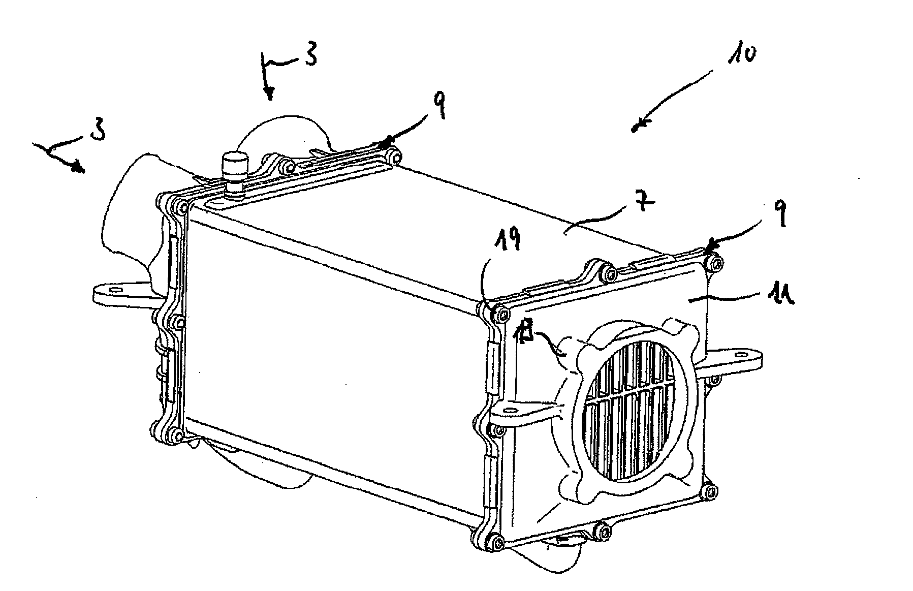
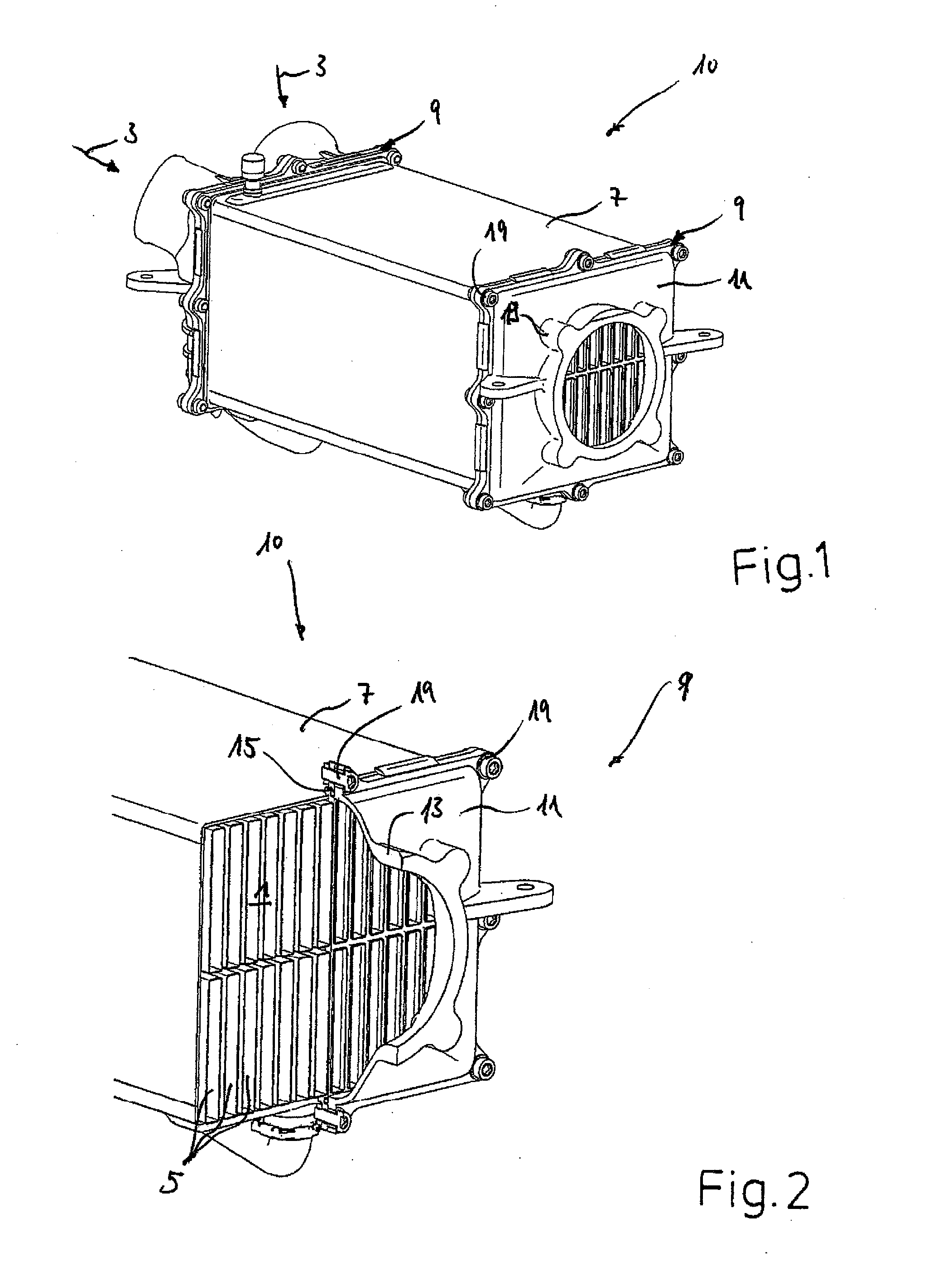
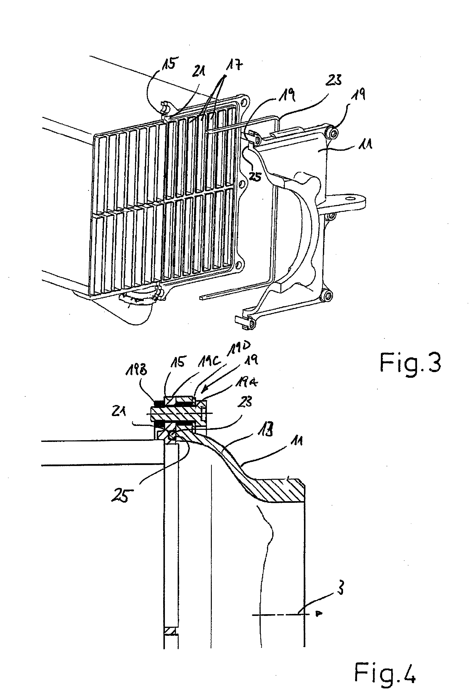
[0061]FIG. 1 shows a heat exchanger 10 in the form of a charge-air cooler for an indirect charge-air cooling, which can be used in a charge-air system for an internal combustion engine. A charge-air system, not shown further, moreover has a charge-air induction, an air filter and a compressor. The heat exchanger 10 represents an exemplary embodiment of the first variant of the invention, according to which a case cover 11 is fixed to a base 15 via several connections, for example, threaded connections 19.

[0062]As is discernible when considering together FIG. 1 and FIG. 2, the heat exchanger 10 has a core 1, which is provided for the guidance separately from one another and in a heat exchanging manner of a first fluid in the form of a charge air 3 as well as a coolant, not shown in further detail. To this end, the core 1 has a number of flow channels 5, which can be flowed through by the charge air 3, as well as a housing 7 that accommodates the flow channels 5 and can be flowed thro...


PUM


Abstract

A heat exchanger, particularly a charge air heat exchanger or exhaust gas heat exchanger, is provided for the heat exchange between a first fluid, particularly a charge air, or an exhaust gas, and a second fluid, particularly a coolant, comprising the following: heat exchanging guides for the first and second fluids, the guides being separated from each other in the core, the core having a plurality of flow channels through which the first fluid flows, and a housing that receives the flow channels and through which the second fluid flows at least one compartment lid, which is flow-connected to the flow channels, and a base that is attached to the compartment lid and that is equipped with one or more passage openings for flow channels. In order to achieve an advantageous connection of the compartment lid to the base, particularly in case the compartment lid and the base are made of different materials, the invention provides that the compartment lid is attached to the base via one or more connections as a bolted connection and / or a slotted crimping.

Description

[0001]This nonprovisional application is a continuation of International Application No. PCT / EP2008 / 002904, which was filed on Apr. 11, 2008, and which claims priority to German Patent Application Nos. DE 102007017330, DE 102007029300, and DE 102008014163, which were filed in Germany on Apr. 11, 2007, Jun. 22, 2007, and Mar. 14, 2008, respectively, and which are all herein incorporated by reference.BACKGROUND OF THE INVENTION[0002]1. Field of the Invention[0003]The present invention relates to a heat exchanger for heat exchange between a first fluid and a second fluid, the heat exchanger includes a core for guidance of the first and second fluid separately from one another and in a heat-exchanging manner, which core has a number of flow channels that can be flowed through by the first fluid and a housing accommodating the flow channels, which housing can be flowed through by the second fluid; at least one case cover that is flow-connected to the flow channels; and a base, which is f...

Claims


Application Information

Patent Timeline
Patent Type & Authority Applications(United States)
IPC IPC(8): F02B29/04F28F9/00
CPCF28D7/1692F28D21/0003F28D2021/0082F02B29/0462F28F2275/122Y02T10/146F28F9/0219Y02T10/12
Inventor BRAIC, VIORELHEMMINGER, ROLANDHENDRIX, DANIELSCHIENEMANN, MARKSKIBA, ERWINKORRIGIEREN, DANIJELKAESER, JOCHEN
Owner MAHLE BEHR GMBH & CO
Learn More