Teatcup liner

Inactive Publication Date: 2010-04-15
DELAVAL HLDG AB
View PDF13 Cites 10 Cited by
  • Summary
  • Abstract
  • Description
  • Claims
  • Application Information

AI Technical Summary

Benefits of technology

[0006]This object is achieved by the teatcup liner initially defined and characterized in that the force application zone seen along the longitudinal centre axis is located within the cross-section area of the milk channel of the tubular lower portion. With such a force application zone the pulling force will be applied at a central position and substantially concentrically with the longitudinal centre axis of the liner. Such a concentration of the pulling force will provide a more efficient pulling of the liner through the shell and to final engagement therein.
[0010]According to a further embodiment of the invention, the grip member comprises two grip elements, which during the mounting state together define the force application zone and are arranged to be gripped simultaneously. By providing two grip elements, manufacturing is easier, and it is still possible to provide a force application zone within the cross-section area of the milk channel.
[0011]According to a further embodiment of the invention, each grip element seen along the longitudinal centre axis is movable from an inactive position outside the cross-section area to an active position within the cross-section area. Such a design of the grip elements is advantageous from a manufacturing point of view. A mould and a core for the moulding of the teatcup liner can then more easily be made than if the grip elements during the manufacturing would be located within the cross-section area of the milk channel of the tubular lower portion. Consequently, the grip elements can in the inactive position extend outside the cross-section area and outside the tubular lower portion and then be bent to the active position within the cross-section area when the teatcup liner is to be mounted, i.e. when the teatcup liner is introduced into the shell and moved therethrough, and then when the grip member is gripped before the final pulling of the teatcup liner to engagement in the shell.
[0014]According to a further embodiment of the invention, the primary engagement member is bendable towards the upper head portion. With such a bendable engagement member, the teatcup liner may be pulled in such a way that the primary engagement member passes over the secondary engagement member. The pulling resistance can be controlled or adapted by varying the bending resistance of the primary engagement member. Advantageously, a hindering member is arranged on the outer side of the tubular lower portion at a small distance from the primary engagement member, thereby rendering the primary engagement member less prone to bend away from the upper head portion then to bend towards the upper head portion. In such away introduction and pulling of the teatcup liner is facilitated whereas the removing is made more difficult so that the teatcup liner will be safely secured in the shell.

Problems solved by technology

However, the vulcanisation of the rubber requires a significant vulcanisation time before the rubber can be removed from the mould and the core.
This is a limiting factor in the manufacturing of teatcup liners.
However, such a pulling operation has to be performed a large number of times when the liners are to be replaced in many teatcups.

Method used


Image

  • Teatcup liner
  • Teatcup liner
  • Teatcup liner

Examples


Embodiment Construction

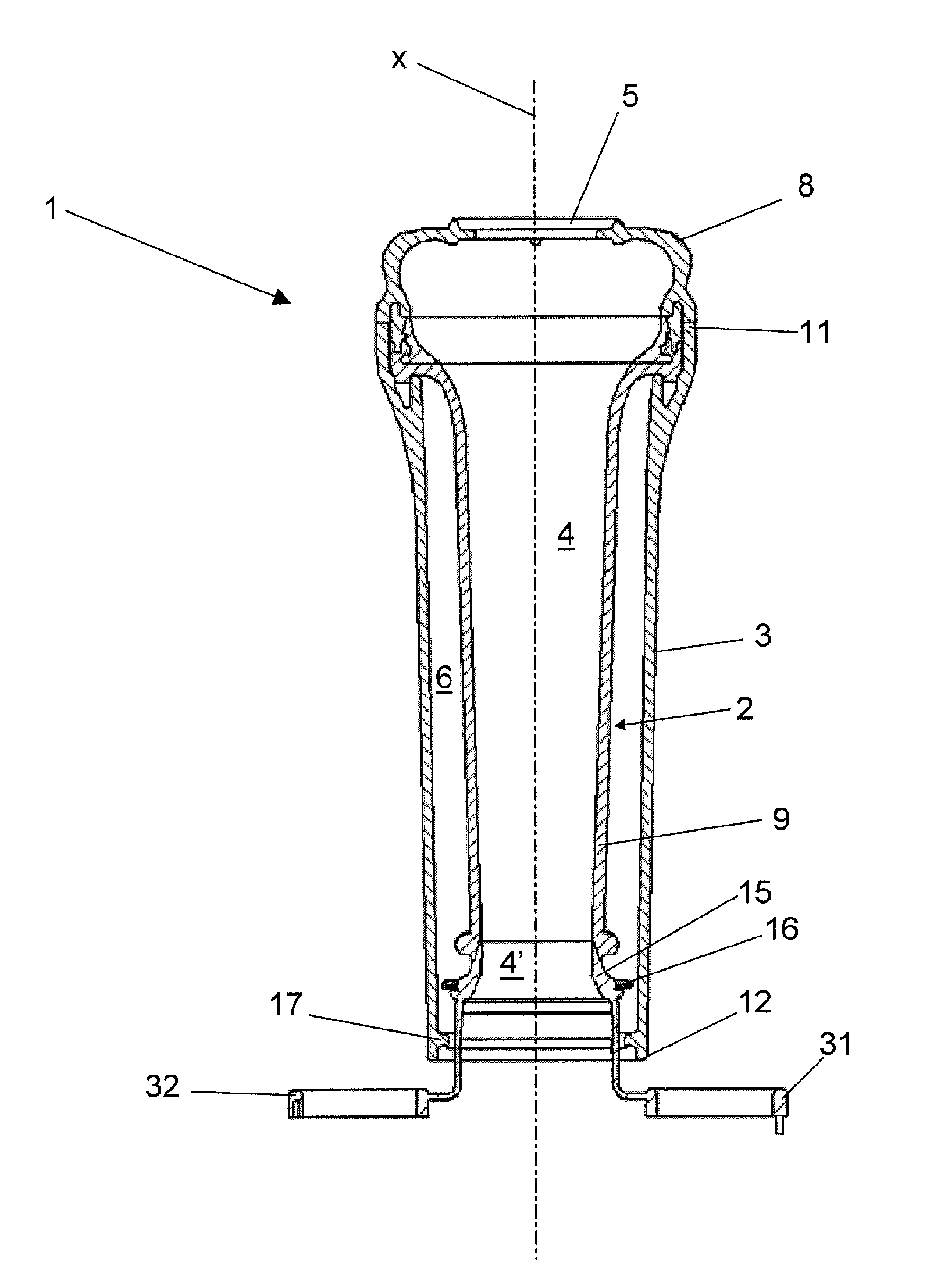
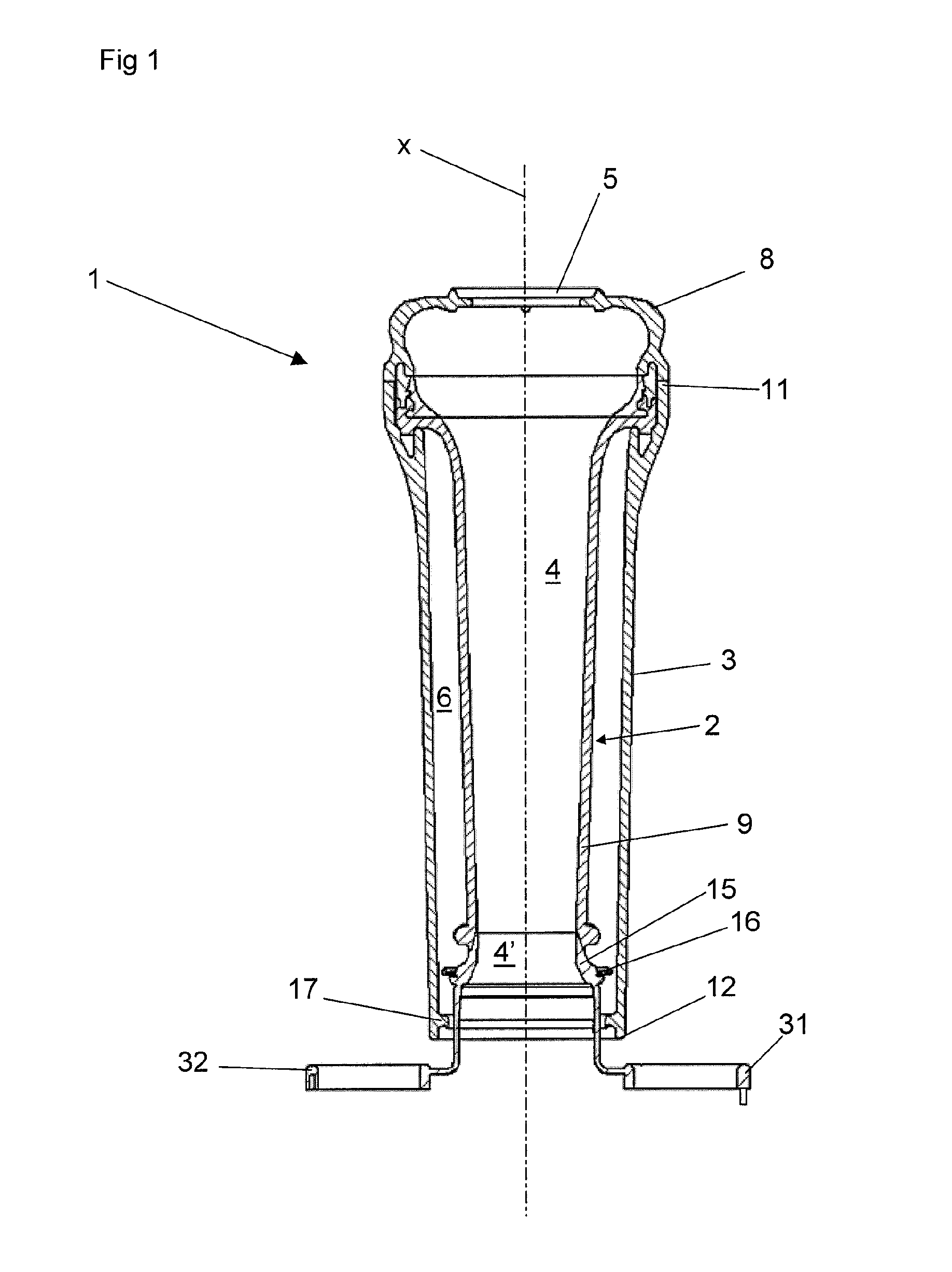
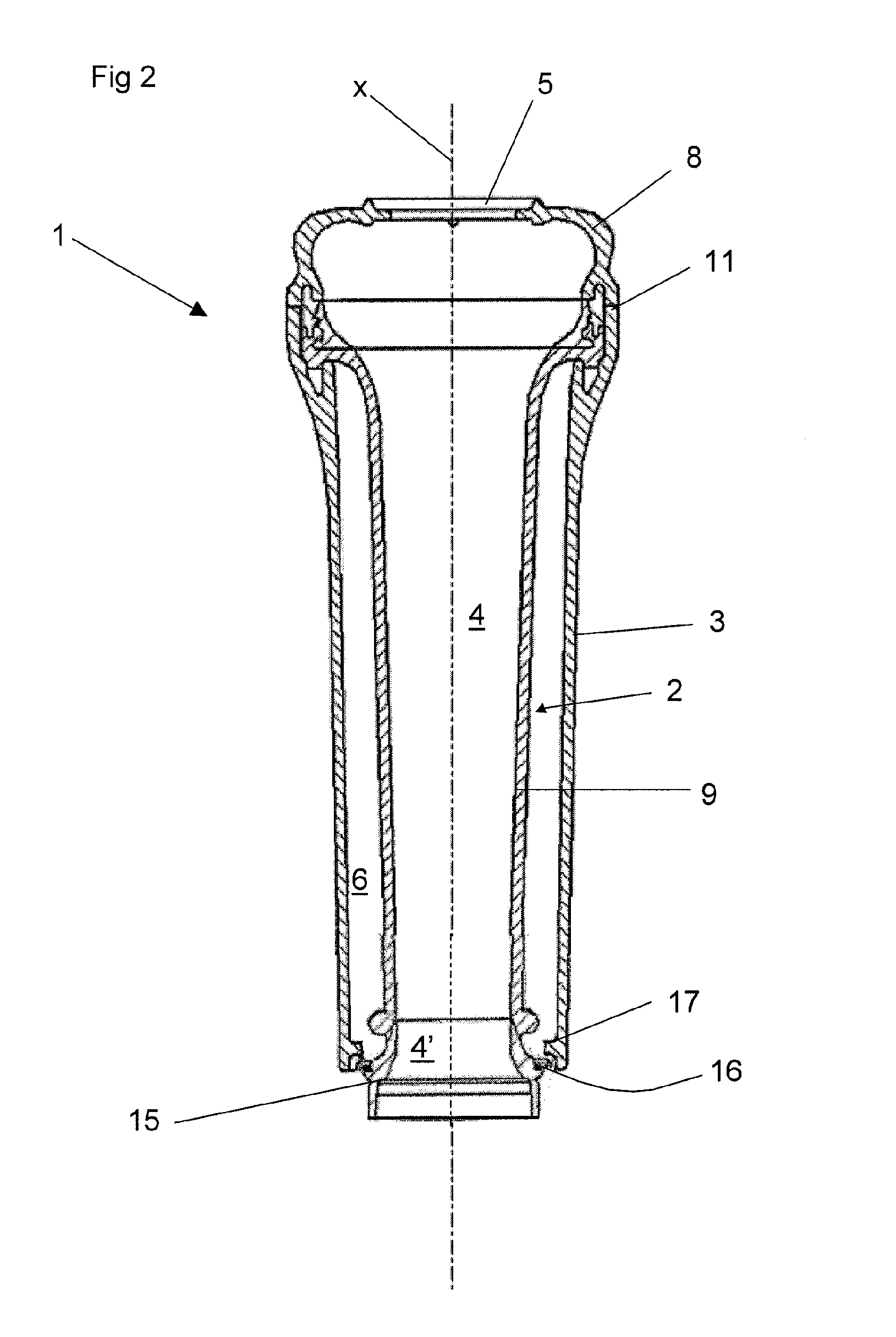
[0031]FIGS. 1 and 2 discloses a teatcup 1 comprising a teatcup liner 2 and a shell. FIG. 1 discloses the teatcup liner 2 introduced into the shell but not finally engaged therein. FIG. 2 discloses a mounted state, in which the teatcup liner 2 is engaged in the shell 3. The teatcup liner 2 includes an inner space 4 adapted to receive a teat of an animal to be milked. The teatcup liner 2 and the inner space 4 extends along a longitudinal centre axis x. A teat of an animal is introduced into the inner space 4 via an upper opening 5. A pulsation chamber 6 is formed between the shell 3 and the teatcup liner 2. The pulsation chamber 6 is accessible via an aperture, e.g. formed by a pipe nipple (not disclosed). In the mounted stated, the teatcup liner 2 comprises an upper head portion 8 and a lower tubular barrel portion 9 of the teatcup liner 2. The shell 3 has an upper end 11 and a lower end 12.

[0032]The head portion 8 and the tubular barrel portion 9 may be separate engaged parts. When ...


PUM


Abstract

A teatcup liner adapted to be mounted in a shell to form a teatcup to be applied to a teat of an animal, and a method of mounting a teatcup liner. The liner defines an inner space for receiving the teat and a longitudinal centre axis. The liner has a head portion, a tubular barrel portion and, a tubular lower portion defining a milk channel having a cross-section area perpendicular to the centre axis. The tubular lower portion has a primary engagement member to be engaged by a secondary engagement member of the shell. The liner includes a grip member extending from the tubular lower portion to be gripped by an operator when the liner is to be mounted. The grip member defines a force application zone on which a pulling force is to be applied and which seen along the centre axis is located within the cross-section area.

Description

BACKGROUND OF THE INVENTION AND PRIOR ART[0001]The present invention refers to a teatcup liner adapted to be mounted in a shell to form a teatcup to be applied to a teat of an animal in accordance with the pre-characterizing portion of claim 1. Such a teatcup liner is disclosed in WO2005 / 120216.[0002]The invention also refers to a teatcup including a teatcup liner and a shell.[0003]Teatcup liners are typically manufactured in a natural or synthetic rubber material. Rubber materials have many advantages connected to the elastic properties of rubber. These elastic properties are advantageous both during the manufacturing of the teatcup liner and during milking. The teatcup liner formed in a mould can easily be removed from the mould and the core shaping the inner space of the teatcup liner after the vulcanisation. However, the vulcanisation of the rubber requires a significant vulcanisation time before the rubber can be removed from the mould and the core. This is a limiting factor in...

Claims


Application Information

Patent Timeline
IPC IPC(8): A01J5/12
CPCA01J5/08
Inventor PETTERSON, TORBJORNKASSIBRAHIM, JAN
Owner DELAVAL HLDG AB
Why Eureka
Try Eureka