
Device and methods for simulating controller area network signals

a controller area network and signal generation technology, applied in the field of devices and methods for simulating controller area network signals, can solve the problems of generating error signals in vehicles, difficult to achieve and maintain, and actual systems cannot always easily produce full range of can signals, etc., to achieve easy and inexpensive generation, easy to upgrade or downgrade, and easy to change the functionality and features.

Inactive Publication Date: 2010-03-18
AU GROUP ELECTRONICS
View PDF1 Cites 32 Cited by
  • Summary
  • Abstract
  • Description
  • Claims
  • Application Information

AI Technical Summary

Benefits of technology

[0016]It is therefore the second aspect of this invention to provide a device to generate new types of CAN signal relatively easily, and to generate multiple types of CAN signals at the same time.
[0017]It is therefore the third aspect of this invention to provide a signal generating device with an easy-to-use feature and an easy-to-read / visualize feature for the CAN signals generated by the device.
[0018]It is therefore the fourth aspect of this invention to provide a signal generating device that the signal generating process is not destructive to actual systems, not time-consuming and is barely environmental hazardous.
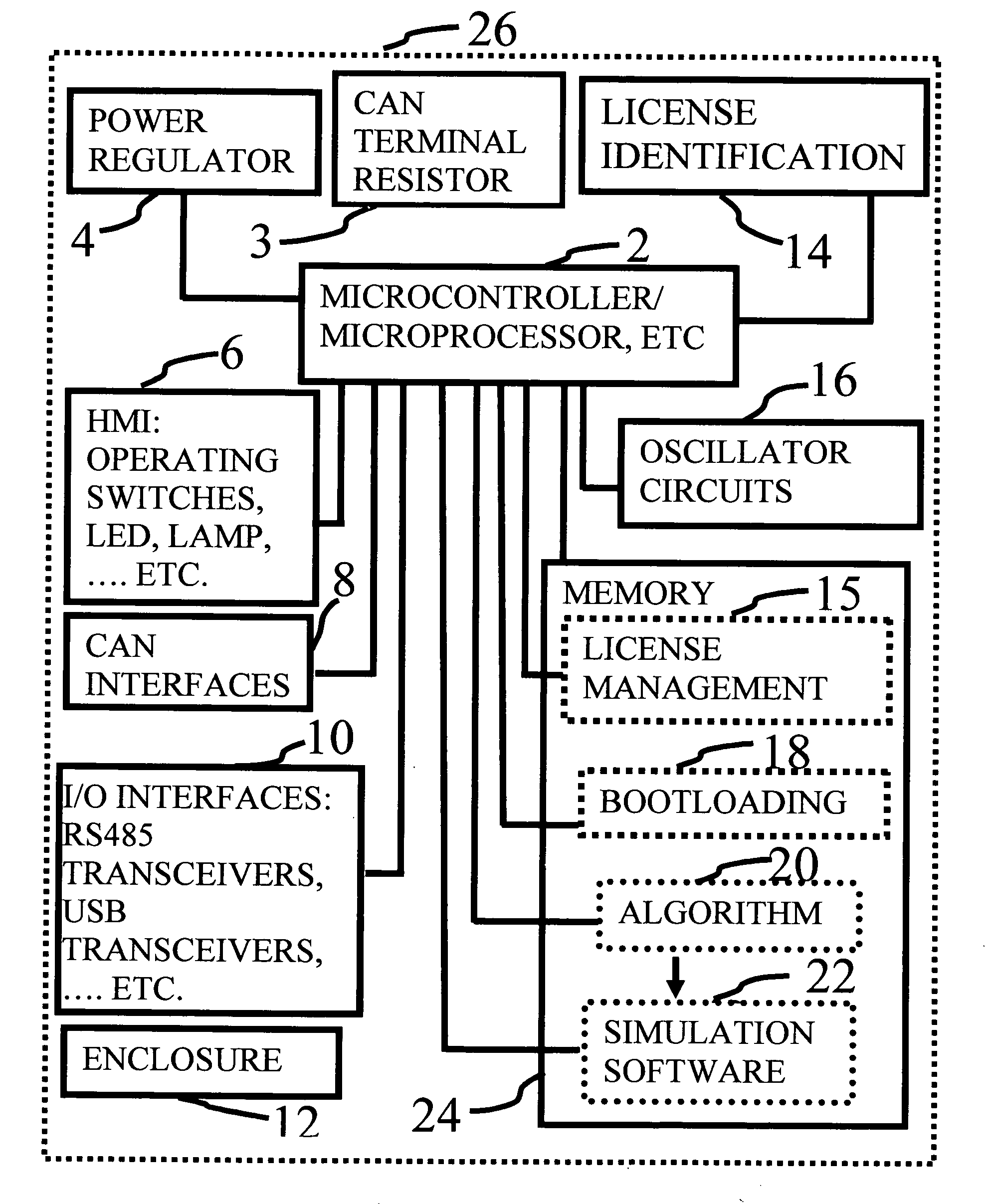
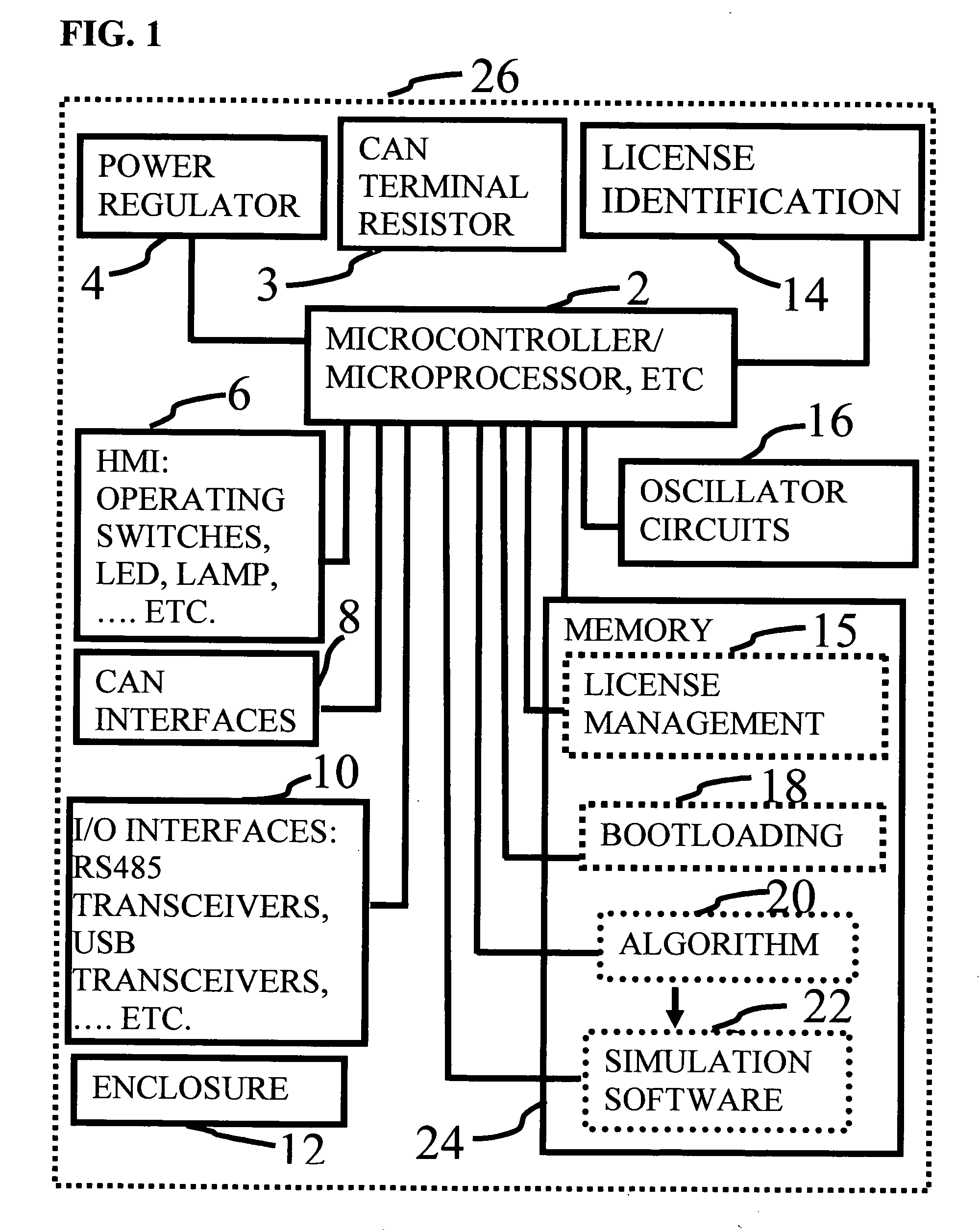
[0020]In this invention, a method of device license identification management system is provided. With this method, the simulation device can be easily upgraded or downgraded to include more or less functions of signal simulation without the need to purchase a new device, without the need of sending the device back to the manufacturer, without the need of any hardware changes, without the need of even opening the enclosure of the device; instead it requires only changing the device license identification through a license identification management system. Therefore, such a signal generating apparatus is able to relatively easily and inexpensively generate new types of CAN signals, and to generate multiple types CAN signals at the same time.
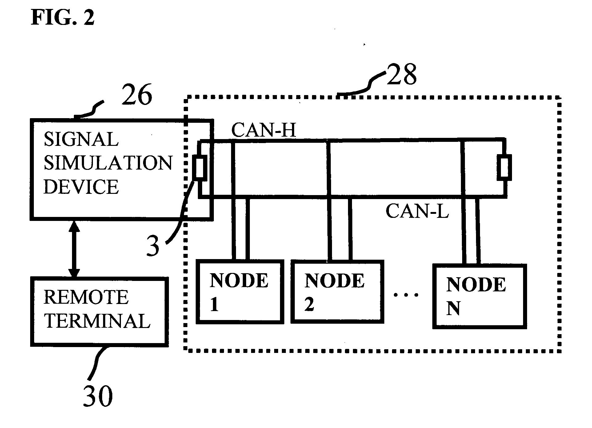
[0021]This device of invention has the plug-and-play feature. No complex installation of hardware is required. The operation of such a device is through operating a push button or similar human machine interface media, or through making commands and selections on a graphic user interface software provided by the remote terminal method and software of this invention. The simulation device itself has a visual display to indicate the values of simulated signals, and it is also capable of producing audible sounds reflecting inputs from human machine interfaces. In addition, the remote terminal of this invention provides a visual access for the signal simulation control and displays precise values of those simulated signals. Therefore, the device has the aspect of easy-to-read / visualize for the CAN signals generated by the device. A method of using the license identification management system in this invention makes it possible for easily changing the functionality and features without any hardware change, without sending the device to the manufacturer, and without even opening the enclosure of the device. The device has an in-field bootloading feature. The bootloading feature makes it easy to refresh the simulation device if errors are found in programming codes. Also, the bootloading feature is very valuable and convenient to add newly released features and functions. All of these aspects combined fulfill the ease-of-use goal of the invention.
[0022]The device is powered by a 12-24 volts power supply; it can be made to occupy very little space in the common CAN application environment and to be so small to fit an adult size palm; it does not need any fuel or water; it does not generate harmful emission by itself; it does not require any maintenance when it is not in use; to generate CAN signals, it does not require a person to operate a real vehicle, a boat, a car, etc. Therefore it is not destructive to an actual system; generating signals by this device is not time-consuming or labor-consuming and the device reduces environmental hazards that might be otherwise produced by actual systems.

Problems solved by technology

However actual systems can not always easily produce a full range CAN signals due to the physical and functionality limits of the actual system.
This is sometimes hard to achieve and maintain.
In another example, if one wants to test the error condition of an antilock braking system in a heavy duty truck, one needs to generate error signals in the vehicle, which is not easily achieved in the field.
Meeting this requirement can be costly.
The size and cost of such a large pool of test equipments can become very challenging.
Also in this case, due to the fact of using multiple actual ECUs, controlling all of the actual systems at the same time or reading / visualizing the signals from all of the systems at the same time is difficult for the testing operator(s).
In other situations, supplying CAN signals can be destructive to the actual system or time-consuming or imposing a lot of environmental hazards.
It may become destructive to the transmission.
In another example, if one needs make full range testing for a vehicle odometer, the process to obtain the high mileages by driving a vehicle with the odometer on board would have imposed a great amount of emissions to the environment, let alone the process is time consuming and costly.

Method used


Image

  • Device and methods for simulating controller area network signals
  • Device and methods for simulating controller area network signals
  • Device and methods for simulating controller area network signals

Examples


Embodiment Construction

[0039]The following established physical layer standards are for Controller Area Network. They are cited in this invention's specification. According to Reference 2, various CAN standards include:[0040]SAE J1939 standard uses a two-wire twisted pair; SAE J1939-11 has a shield around the pair while SAE J1939-15 does not. SAE 1939 is widely used in agricultural & construction equipment.[0041]ISO 11898-1 includes protocols of Controller Area Network data link layer and physical signaling.[0042]ISO 11898-2 uses a two-wire balanced signaling scheme. It is the most used physical layer in car powertrain applications and industrial control networks.[0043]ISO 11898-3 includes protocols of Controller Area Network low-speed, fault-tolerant, medium-dependent interface.[0044]ISO 11898-4 standard defines the time-triggered communication on CAN (TTCAN). It is based on the CAN data link layer protocol providing a system clock for the scheduling of messages.[0045]ISO 11898-5 includes protocols of Co...


PUM


Abstract

The invention relates to a device of generating simulation signals for Controller Area Network (CAN). The device in this invention simulates CAN data streams normally generated by electronic control units (ECUs) in automobiles, vehicles, boats, etc. without the presence of these ECUs. The device in this invention has a visual display of simulated signals' values. In addition, this invention reveals a remote terminal method and software. The remote terminal software in this invention can control the simulated signal via graphic user interfaces. The remote terminal software in this invention also displays the precise values of simulated signals via graphic user interfaces. Furthermore, this invention presents an advantageous method using a license identification management technique to change the functionality and features of the simulation device without any hardware modifications and without sending the device back to the device manufacturer.

Description

CROSS-REFERENCE TO RELATED APPLICATIONS[0001]Not Applicable.STATEMENT REGARDING FEDERALLY SPONSORED RESEARCH OR DEVELOPMENT[0002]Not Applicable.REFERENCE TO SEQUENCE LISTING, A TABLE, OR A COMPUTER PROGRAM LISTING COMPACT DISC APPENDIX[0003]Not Applicable.REFERENCES CITED-PUBLICATIONS[0004]1. <http: / / en.wikipedia.org / wiki / Controller_Area_Network>—“Controller-area Network, From Wikipedia, the free encyclopedia”.[0005]2. <http: / / en.wikipedia.org / wiki / Controller_Area_Network>—“Controller-area Network, Standards”.[0006]3. <http: / / www.auelectronics.com / UserManual.htm>—“User Manual for SAE-J1939 Simulator (Gen II)”, Copyright 2008 Au Group Electronics.[0007]4. <http: / / www.auelectronics.com / UserManual.htm>—“License Management User Manual for SAE-J1939 Simulator”, Copyright 2008 Au Group Electronics.[0008]5. <http: / / www.auelectronics.com / UserManual.htm>—“AU SAE-J1939 Simulator Remote Terminal Installation Guide”, Copyright 2008 Au Group Electronics.[0009]6. <...

Claims


Application Information

Patent Timeline
IPC IPC(8): H04L9/32G06F17/10H04L9/08G06F15/177G09F9/33
CPCH04L12/40006H04L67/12H04L2012/40267H04L2012/40215
Inventor DUAN, HUIHUICHEN, CHAONANDUAN, MINGMING
Owner AU GROUP ELECTRONICS
Learn More