Short-body plug for fluid couplings

a technology of fluid couplings and plugs, applied in the direction of pipe joints, pipe/joints/fittings, adjustable joints, etc., can solve the problem of plugs being made correspondingly long

Active Publication Date: 2010-03-18
RECTUS
View PDF20 Cites 2 Cited by
  • Summary
  • Abstract
  • Description
  • Claims
  • Application Information

AI Technical Summary

Benefits of technology

[0021]FIG. 1 cross-sectional view of a fluid coupling including a short-body plug in accordance with the present invention and an associated coupler.

Problems solved by technology

The plug is made correspondingly long, which is especially problematic when the plug is attached to a stiff, immovable part, for example a cylinder valve.

Method used


Image

  • Short-body plug for fluid couplings
  • Short-body plug for fluid couplings

Examples


Embodiment Construction

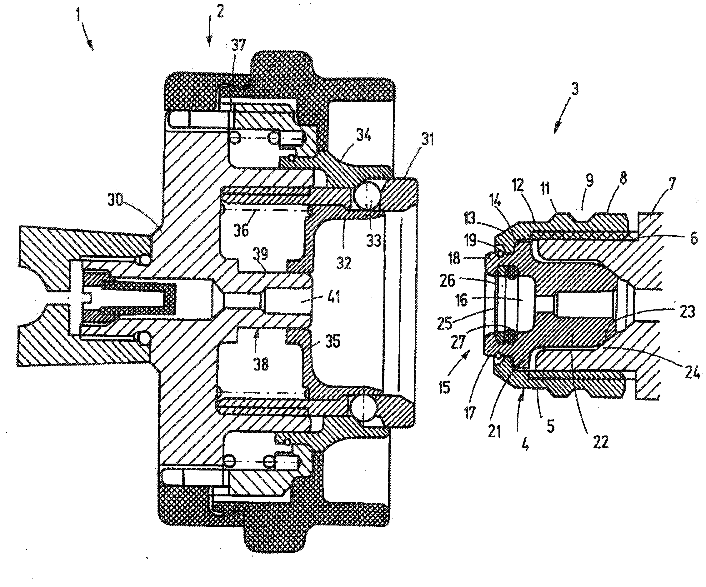
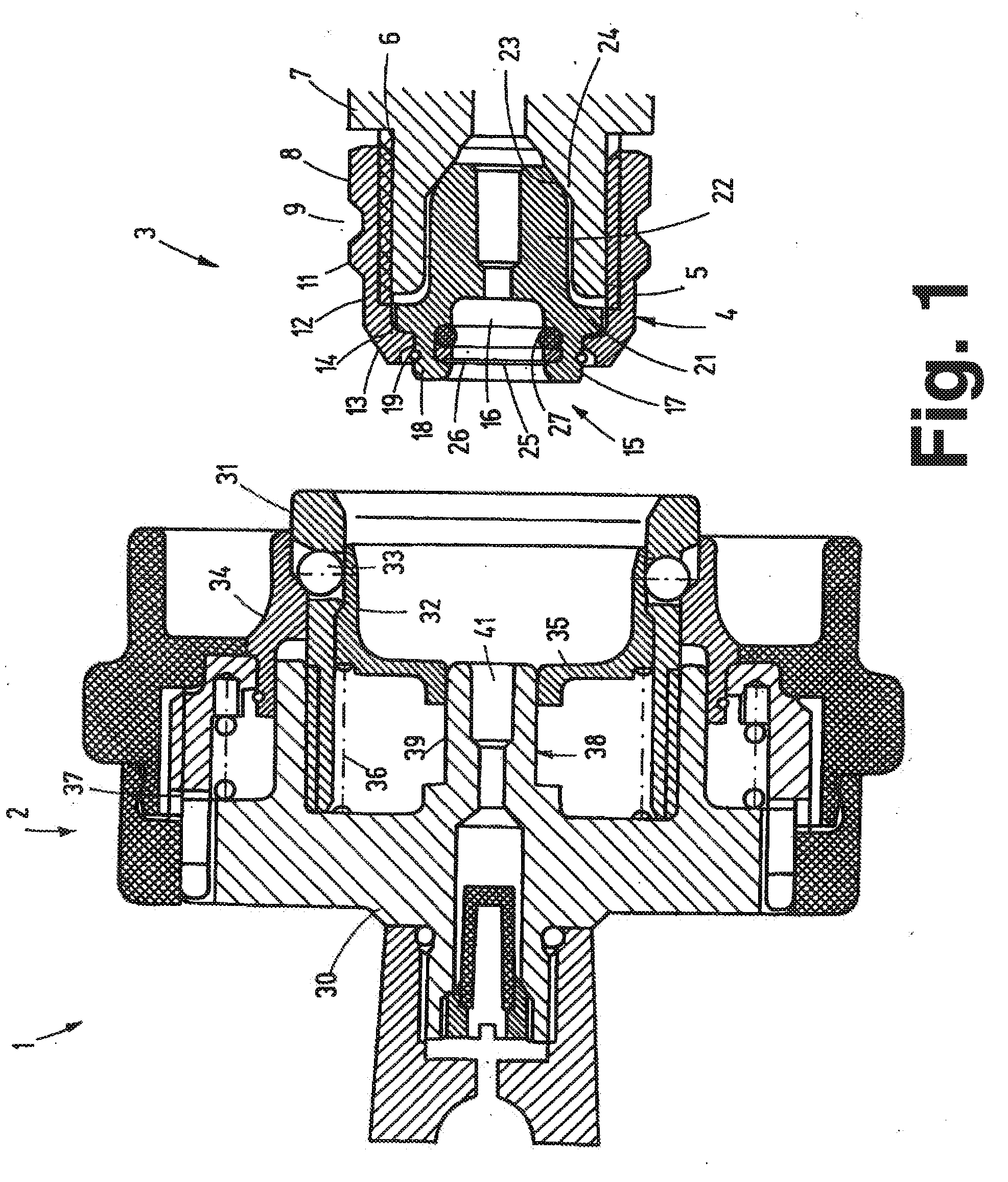
[0023]FIG. 1 shows a fluid-coupling arrangement 1 in the uncoupled state. The coupling arrangement 1 includes a coupler 2 and a plug 3 according to the invention that can be plugged into the coupler 2.

[0024]The plug 3 has a sleeve-like body 4, which is provided with an inner thread 5. With the aid of the inner thread 5, the body 4 can be screwed onto an outer thread 6 of a cylinder valve, of which only the thread support 7 can be recognized. The outside of the body 4 has rotation symmetry and carries at its back end, i.e., at the end away from the coupler 2, a hexagon 8 as a tool-gripping surface. Directly adjacent to the hexagon 8, a circumferential groove 9 with a trapezoidal cross-section is present, which goes over to the insertion end of the plug 3 into a rib 11. When connected to the rib 11, the outer circumferential surface of the body 4 is at first a cylindrical surface 12 in design, which goes over into a beveled milled surface 13 at its free end.

[0025]At the height of the ...


PUM


Abstract

A short-body connector for fluid couplings made of a sleeve-shaped body. In the sleeve-shaped body an internal thread is provided, by which the connector can be screwed onto a threaded connection. Relative to axial extension, the locking groove and locking rib serving to hold the connector in the coupler are located at the height of the thread. That is, the locking rib and locking groove located ahead of the thread in the state of the art have moved to the region of the thread in the arrangement according to the invention.

Description

CROSS-REFERENCE TO RELATED CASES[0001]This application is a continuation of copending International Application No. PCT / EP2008 / 002396, filed Mar. 27, 2008, which designated the United States, and which claims priority to German Patent Application No. 10 2007 0179105, filed Apr. 13, 2007, the disclosure of which is expressly incorporated herein by reference.BACKGROUND OF THE INVENTION[0002]The present invention relates broadly to fluid couplings having a female member or coupler and a male member or plug, and more particularly to a short-body plug for such couplings.[0003]Detachable fluid couplings are used to connect fluid lines. The fluid coupling includes a coupler and a plug that can be plugged into the coupler. Within the coupler, there are locking elements that hold the plug in the coupler, so that it is not pushed out by the hydraulic force of the fluid. In addition, capturing means can also be contained in the coupler, that hold the plug in an intermediate position, so that f...

Claims


Application Information

Patent Timeline
Patent Type & Authority Applications(United States)
IPC IPC(8): F16L27/00
CPCF16L37/23
Inventor SIMON, HORSTWITT, STEFAN
Owner RECTUS
Why Eureka
Try Eureka