Air Spring For A Motor Vehicle

a technology for air springs and motor vehicles, applied in mechanical devices, shock absorbers, transportation and packaging, etc., can solve the problems of substantially unsusceptible defects and a simple, extensive mechanical construction

Active Publication Date: 2018-08-02
ZF FRIEDRICHSHAFEN AG
View PDF8 Cites 0 Cited by
  • Summary
  • Abstract
  • Description
  • Claims
  • Application Information

AI Technical Summary

Benefits of technology

[0022]This is particularly advantageous when the air spring is a component part of a driver's cab bearing in a motor vehicle so that the driver's cab is kept in a steady position to a great extent regardless of movements during the driving operation of the motor vehicle.

Problems solved by technology

This configuration has a substantially simple mechanical construction that is extensively unsusceptible to driving operation forces acting upon it.
Therefore, it is substantially unsusceptible to defects.

Method used


Image

  • Air Spring For A Motor Vehicle
  • Air Spring For A Motor Vehicle
  • Air Spring For A Motor Vehicle

Examples


Embodiment Construction

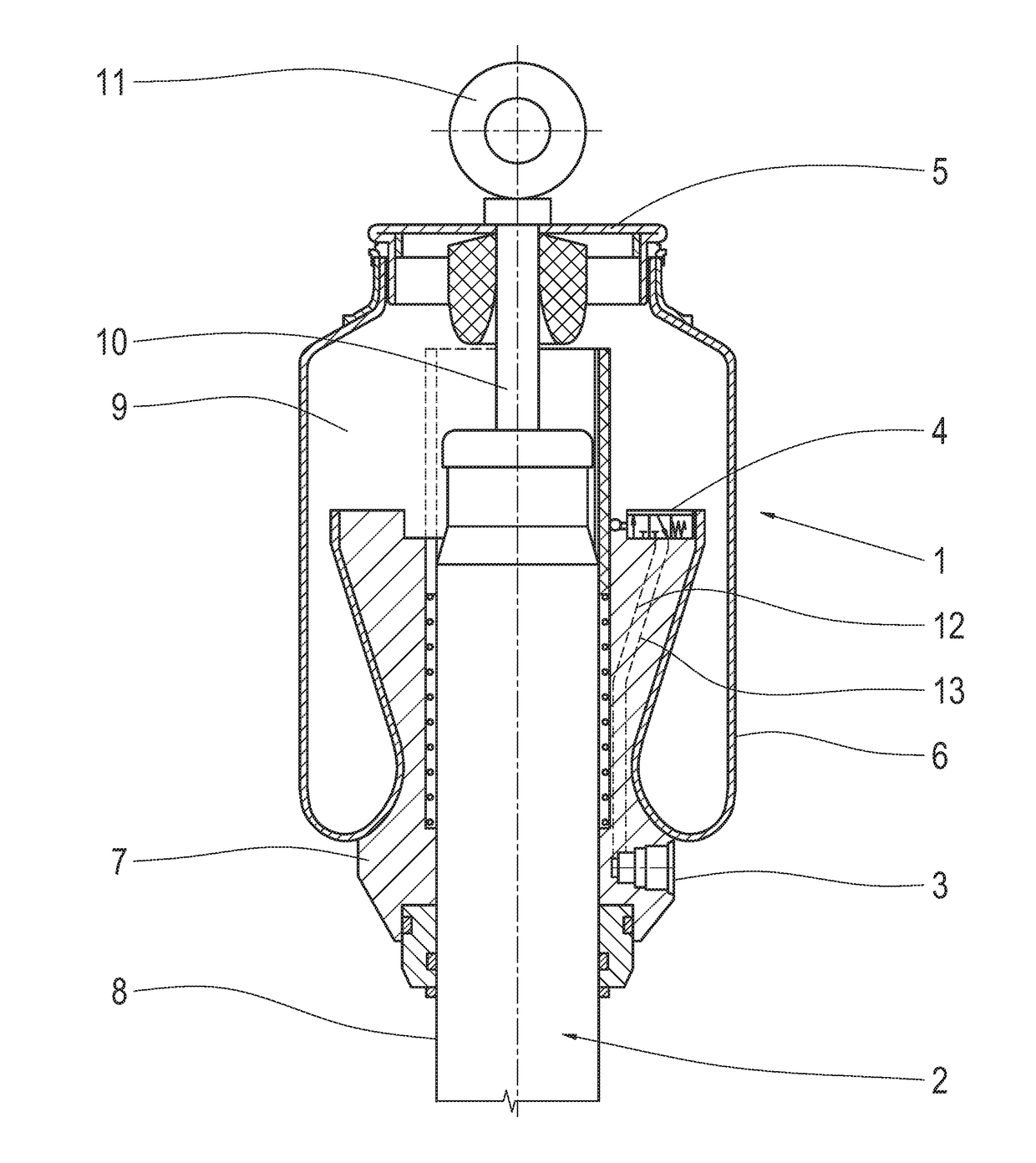
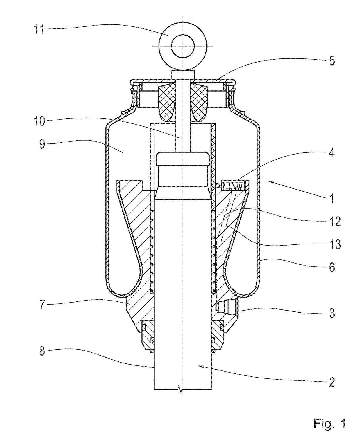
[0035]The air spring unit in FIG. 1 comprises an air spring 1 and a vibration damper 2 arranged concentric to the air spring 1. The air spring 1 is connected to a pressure source, not shown, via a supply connection 3 with the intermediary of a control valve 4.

[0036]The air spring 1 has a cap-like load receiver 5 to which the one end of a rolling bellows 6 is fastened, while the other end of the rolling bellows 6 is fastened to a roll-off piston 7.

[0037]The roll-off piston 7 has a continuous, concentric recess into which a receptacle tube 8 of the vibration damper 2 is tightly inserted.

[0038]The interior 9 of the rolling bellows 6 is filled with a gas under pressure.

[0039]A piston rod 10 of the vibration damper 2 projects through the interior 9 of the rolling bellows 6 and is supportively connected to the load receiver by its free end area. The free end of the piston rod 10 protrudes from the interior 9 and has a fastening element 11.

[0040]The control valve 4 is fastened to the roll-...


PUM


Abstract

An air spring for a motor vehicle having a rolling bellows filled with gas under pressure, one end of the rolling bellows is connected to a load receiver and the other end is fastened to a roll-off piston’. The load receiver and the roll-off piston are moveable relative to one another depending on a force impinging on the load receiver toward the roll-off piston. A sensor device is arranged inside the rolling bellows by which a distance between the load receiver and the roll-off piston is detected. A pressure piece extending in direction of the roll-off piston is arranged at the load receiver and a sensor body is movably drivable along a sensor track of the sensor device by an end region of the pressure piece facing the roll-off piston. The sensor device generates an electric signal corresponding to the position of the sensor body on the sensor track.

Description

CROSS REFERENCE TO RELATED APPLICATIONS[0001]This is a U.S. national stage of application No. PCT / EP2016 / 068273, filed on Aug. 1, 2016. Priority is claimed on German Application No. DE102015216956.1, filed Sep. 4, 2015, the content of which is incorporated here by reference.BACKGROUND OF THE INVENTION1. Field of the Invention[0002]The invention is directed to a rolling bellows filled with gas under pressure, one end of the rolling bellows is connected to a cap-like load receiver and the other end of the rolling bellows is fastened to a roll-off piston. The load receiver and the roll-off piston are moveable relative to one another depending on a force impinging on the load receiver toward the roll-off piston. A sensor device is arranged inside the rolling bellows by which the distance between the load receiver and the roll-off piston can be detected and a corresponding electric signal can be generated.2. Description of the Prior Art[0003]Air springs of this type are used inter alia f...

Claims


Application Information

Patent Timeline
Patent Type & Authority Applications(United States)
IPC IPC(8): F16F9/05B60G17/019
CPCF16F9/057B60G17/019F16F9/361F16F2230/08B60G2202/152B60G2204/111B60G2400/252B60G11/27B60G17/0521F16F9/3292F16F9/05F16F2230/0052F16F2232/06
Inventor NOWOTKA, THOMASMEMMEL, ALFREDMEMMEL, GEORG
Owner ZF FRIEDRICHSHAFEN AG
Why Eureka
Try Eureka