Compressor arrangement

a compressor arrangement and compressor technology, applied in mechanical equipment, non-positive displacement pumps, liquid fuel engines, etc., can solve the problem of rotor-dynamic limitations, the maximum possible pressure build-up of such a compressor arrangement, etc., to achieve the effect of reducing the construction length of such compressor arrangement and increasing the pressure build-up

Active Publication Date: 2017-09-05
MAN ENERGY SOLUTIONS SA
View PDF9 Cites 0 Cited by
  • Summary
  • Abstract
  • Description
  • Claims
  • Application Information

AI Technical Summary

Benefits of technology

[0009]With the present invention it is proposed, in the case of a compressor arrangement having an axial compressor and a radial compressor with a common shaft, to raise the diameter of the shaft in the region of the axial compressor, namely such that the maximum diameter of the shaft in the region of the axial compressor is at least 50% larger than the minimum radial impeller seat diameter of the shaft in the region of the radial compressor. Because of this, the pressure build-up that can be provided can be increased relative to known compressor arrangements and the construction length of such compressor arrangements can be shortened.

Problems solved by technology

The maximum possible pressure build-up of such a compressor arrangement is rotor-dynamically limited.

Method used


Image

  • Compressor arrangement
  • Compressor arrangement

Examples


Embodiment Construction

[0014]The present invention relates to a compressor arrangement of an at least single-stage axial compressor and an at least single-stage radial compressor.

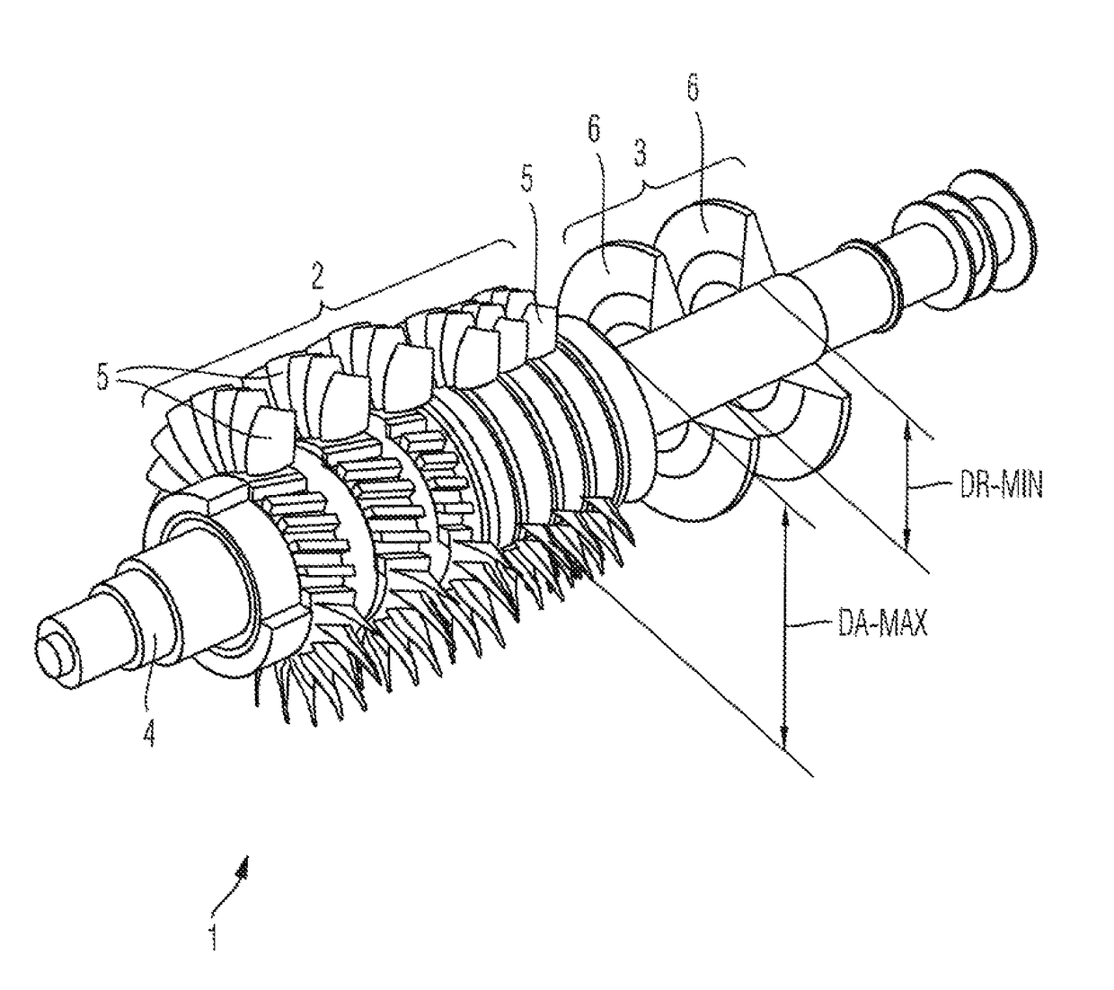
[0015]FIG. 1 shows a schematic, perspective lateral view of assemblies of an exemplary embodiment of a compressor arrangement 1 according to the invention on the rotor side, the compressor arrangement 1 of FIG. 1 comprising a multi-stage axial compressor 2 and a multi-stage radial compressor 3. In the illustrated exemplary embodiment, the axial compressor 2 comprises seven axial compressor stages and the radial compressor 3 comprises two radial compressor stages, wherein axial compressor 2 and radial compressor 3 are axially attached one behind the other or next to one another on a common shaft 4. Accordingly, FIG. 1 shows that moving blades 5 of the axial compressor 2 on the rotor side and radial impellers 6 of the radial compressor stage 3 are attached or fastened to the common shaft 4 axially one behind the other or next to on...


PUM


Abstract

A compressor arrangement has a common shaft, an axial compressor having at least a single-stage, and a radial compressor having at least single-stage. Assemblies of the, or each, axial compressor stage on the rotor side and assemblies of the, or each, radial compressor stage on the rotor side are attached to a common shaft (4). A ratio between a maximum diameter of the shaft (4) in the region of the axial compressor (2) and a minimum radial impeller seat diameter of the shaft (4) in the region of the radial compressor (3) is between 1.5 and 3.0.

Description

BACKGROUND OF THE INVENTION[0001]1. Field of the Invention[0002]The invention relates to a compressor arrangement.[0003]2. Description of the Related Art[0004]From DE 10 2009 016 392 A1, the content of which is incorporated herein by reference in its entirety, a compressor arrangement having an axial compressor and a radial compressor is known, which are arranged axially behind one another on a common shaft. According to DE 10 2009 016 392 A1, assemblies of the, or each, axial compressor stage of the axial compressor on the rotor side and assemblies of the, or each radial compressor stage of the radial compressor on the rotor side accordingly are arranged on the common driveshaft or fastened on the same.[0005]The maximum possible pressure build-up of such a compressor arrangement is rotor-dynamically limited. Accordingly, the pressure build-up is limited in particular through the natural frequency, the stiffness and the damping characteristic of the assemblies of the compressor arra...

Claims


Application Information

Patent Timeline
Patent Type & Authority Patents(United States)
IPC IPC(8): F04D17/02F02C3/08F04D29/66F01D5/14F02C3/14
CPCF04D17/025F01D5/143F02C3/08F04D29/666F02C3/14F04D25/16
Inventor HORMEYER, KLAUSEMMRICH, ROLANDEISENBERG, BERNHARDANDING, DIRKRESSING, HENNING
Owner MAN ENERGY SOLUTIONS SA
Why Eureka
Try Eureka