Belt buckle with release lock
a belt buckle and lock technology, applied in the field of belt buckles, can solve the problems of the belt buckle opening automatically risk, and achieve the effect of convenient integration and inexpensive manufacturing
- Summary
- Abstract
- Description
- Claims
- Application Information
AI Technical Summary
Benefits of technology
Problems solved by technology
Method used
Image
Examples
first embodiment
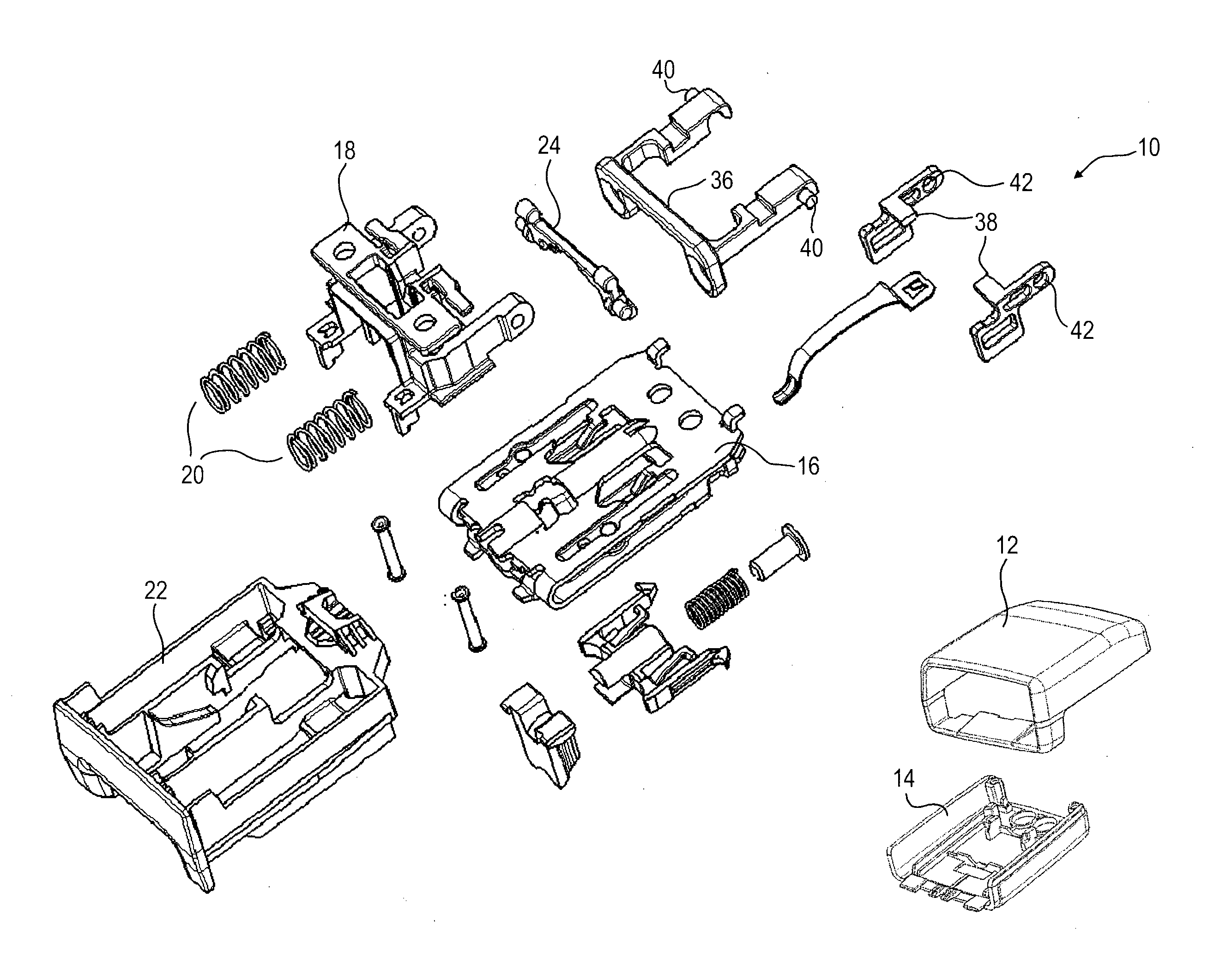
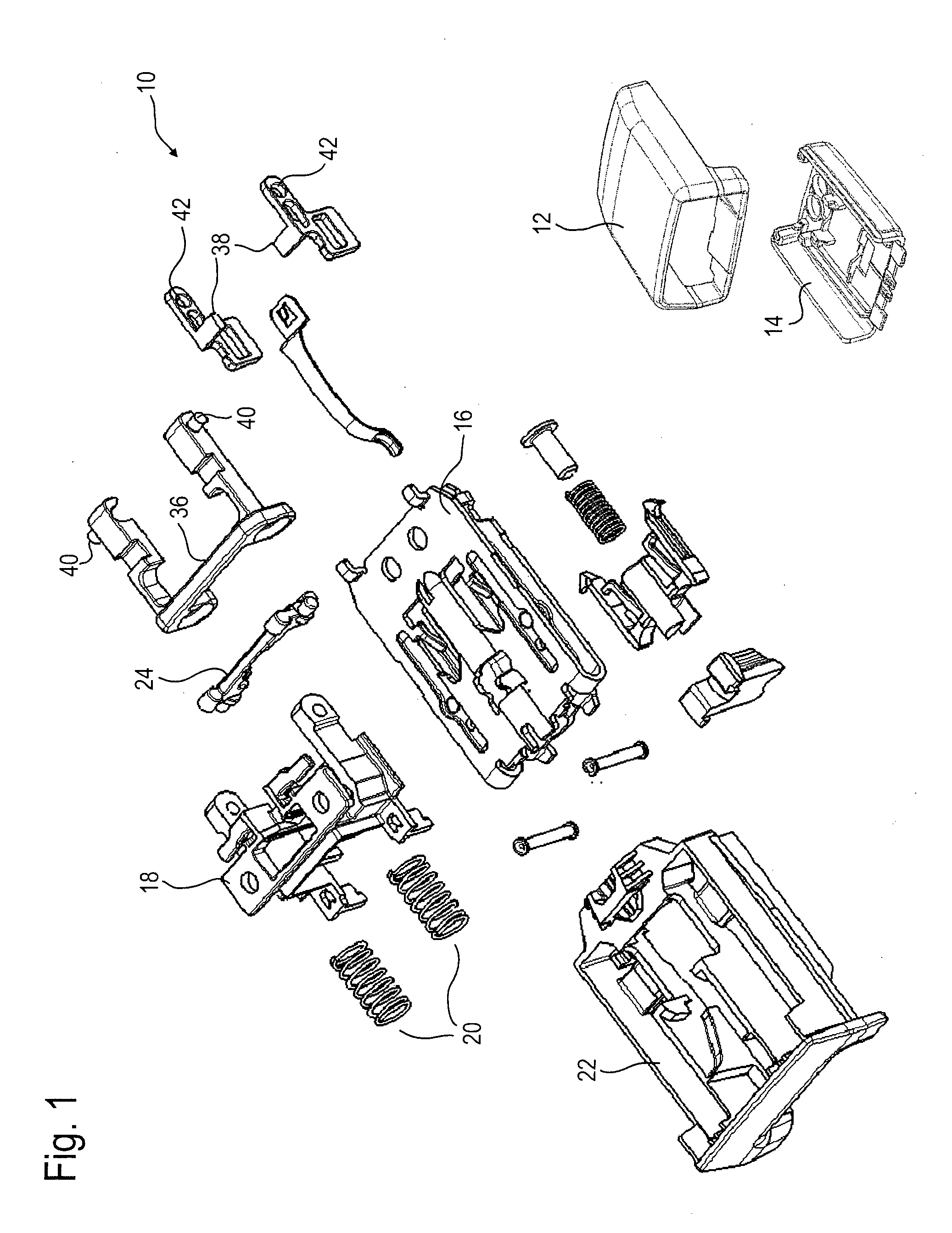
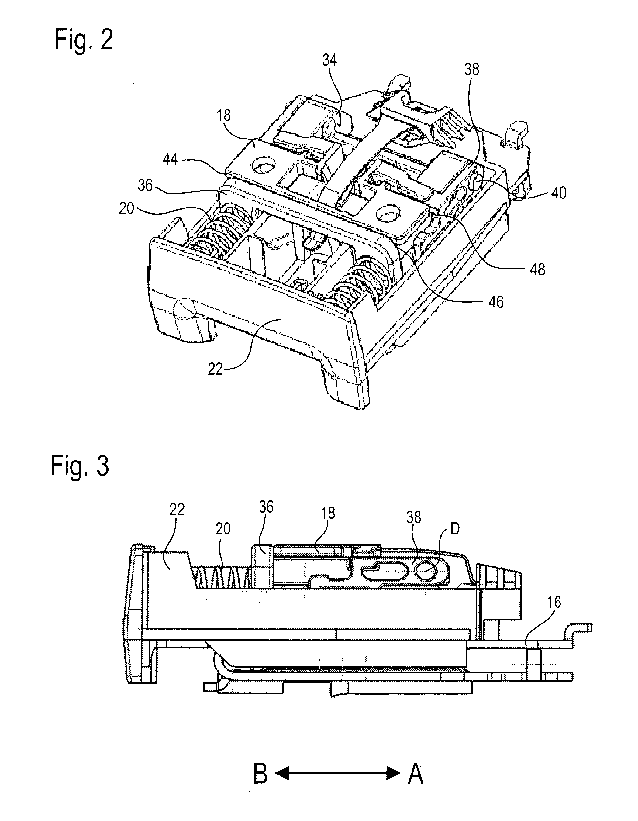
[0035]In FIGS. 1 to 11 a belt buckle 10 for a seat belt system is represented which is mounted tightly on the vehicle at a fitting, which is not shown, either directly or by a belt tensioner connected to the fitting. The housing shells 12, 14 are omitted in the FIGS. 2 to 11 so as to allow an unhindered view onto the inner components of the belt buckle 10. Hereinafter, among the components shown in FIG. 1 only the components relevant to the invention shall be discussed, as the basic structure and the basic functioning of a belt buckle 10 are provided as being known.
[0036]A detent cam guide 18 is fixedly mounted on a load-bearing buckle housing 16. Two compression springs 20 pretension a release button 22 configured in the form of a slide and being movable relative to the housing in the directions A and B in the direction (second direction) B opposite to the actuating direction (first direction) A.
[0037]A two-armed coupling lever 24 is rotatably supported on the detent cam guide 18 ...
second embodiment
[0047]In FIGS. 12 and 13 a belt buckle for a seat belt system is illustrated that exhibits a structure similar to the afore-described belt buckle 10 shown in FIGS. 1 to 11. Therefore, the same reference numerals have been used for corresponding components having the same function despite certain deviations in the concrete configuration, and in this respect the foregoing explanations concerning said components are referred to.
[0048]The substantial difference between the two embodiments consists in the fact that the belt buckle according to the second embodiment has a shorter overall length, because no pivot bodies 38 are provided. However, the retaining portion 48 is formed at the coupling lever 24 which is cranked. Accordingly, the holding portion 50 of the detent cam guide 18 fixed to the housing is arranged in a position opposite to the retaining portion 48. The interaction of the retaining portion 48 with the holding portion 50 shall be described in detail later.
[0049]FIG. 12 sh...
PUM
 Abstract
Description
Claims
Application Information
 - R&D
- Intellectual Property
- Life Sciences
- Materials
- Tech Scout
- Unparalleled Data Quality
- Higher Quality Content
- 60% Fewer Hallucinations
Browse by: Latest US Patents, China's latest patents, Technical Efficacy Thesaurus, Application Domain, Technology Topic, Popular Technical Reports.
© 2025 PatSnap. All rights reserved.Legal|Privacy policy|Modern Slavery Act Transparency Statement|Sitemap|About US| Contact US: help@patsnap.com


