
Ct imaging system

a technology of ct imaging and flow values, applied in the field of ct imaging systems, can solve the problems of reducing and achieve the effect of increasing the quality of determined flow values

Active Publication Date: 2010-03-11
KONINKLIJKE PHILIPS ELECTRONICS NV
View PDF6 Cites 13 Cited by
  • Summary
  • Abstract
  • Description
  • Claims
  • Application Information

AI Technical Summary

Benefits of technology

[0004]It is therefore an object of the present invention to provide a CT imaging system wherein the influence of the determination of the flow values by effects related to the passage of the X-ray radiation through the object is reduced, thereby increasing the quality of the determined flow values. Further, a corresponding CT imaging method, a corresponding determination device and a corresponding determination method shall be provided.
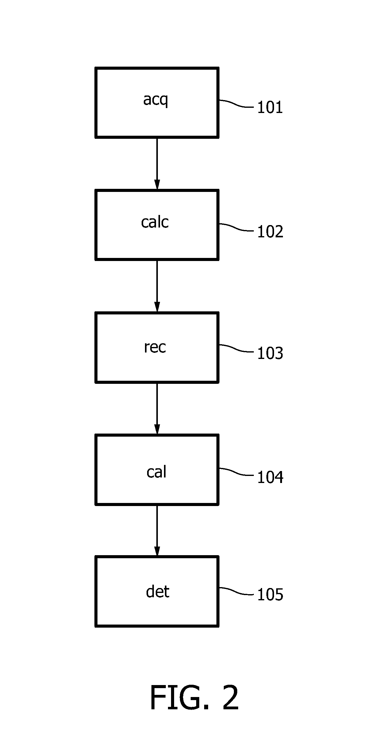
[0011]The present invention is based on the idea that a k-edge component of the substance is determined from the detection signals and that a time series of k-edge images is reconstructed from the determined k-edge component. This leads to reconstructed images only containing the substance, i.e., the object itself is not contained in the image. These images of the substance are therefore not disturbed by the object. Since these images containing only the substance are used for determining the flow values, the influence of the flow values by effects related by to the passage of the X-ray radiation through the object is reduced, thereby increasing the quality of the determined flow values.
[0017]In a further preferred embodiment a model is used which takes account of the emission spectrum of the X-ray source and the spectral sensitivity of the X-ray detector in each of the plurality of energy bins. That leads to higher accuracy of the calculated components and, thus, of the reconstructed images and of the determined flow values.

Problems solved by technology

This diminishes the quality of the determined flow values.

Method used


Image

  • Ct imaging system
  • Ct imaging system
  • Ct imaging system

Examples


Embodiment Construction

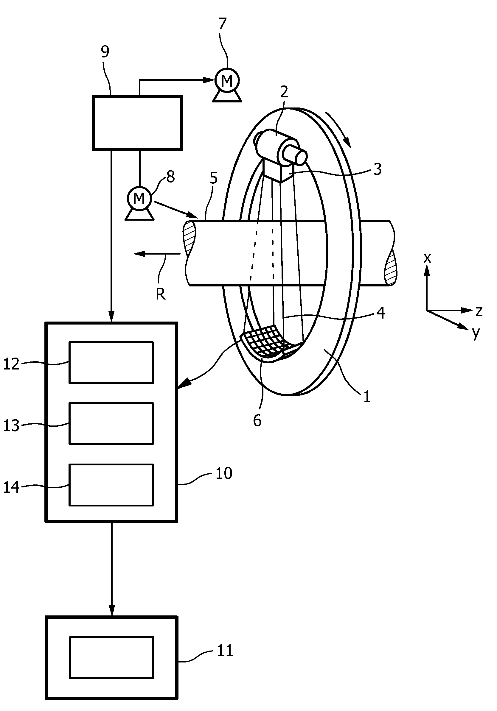
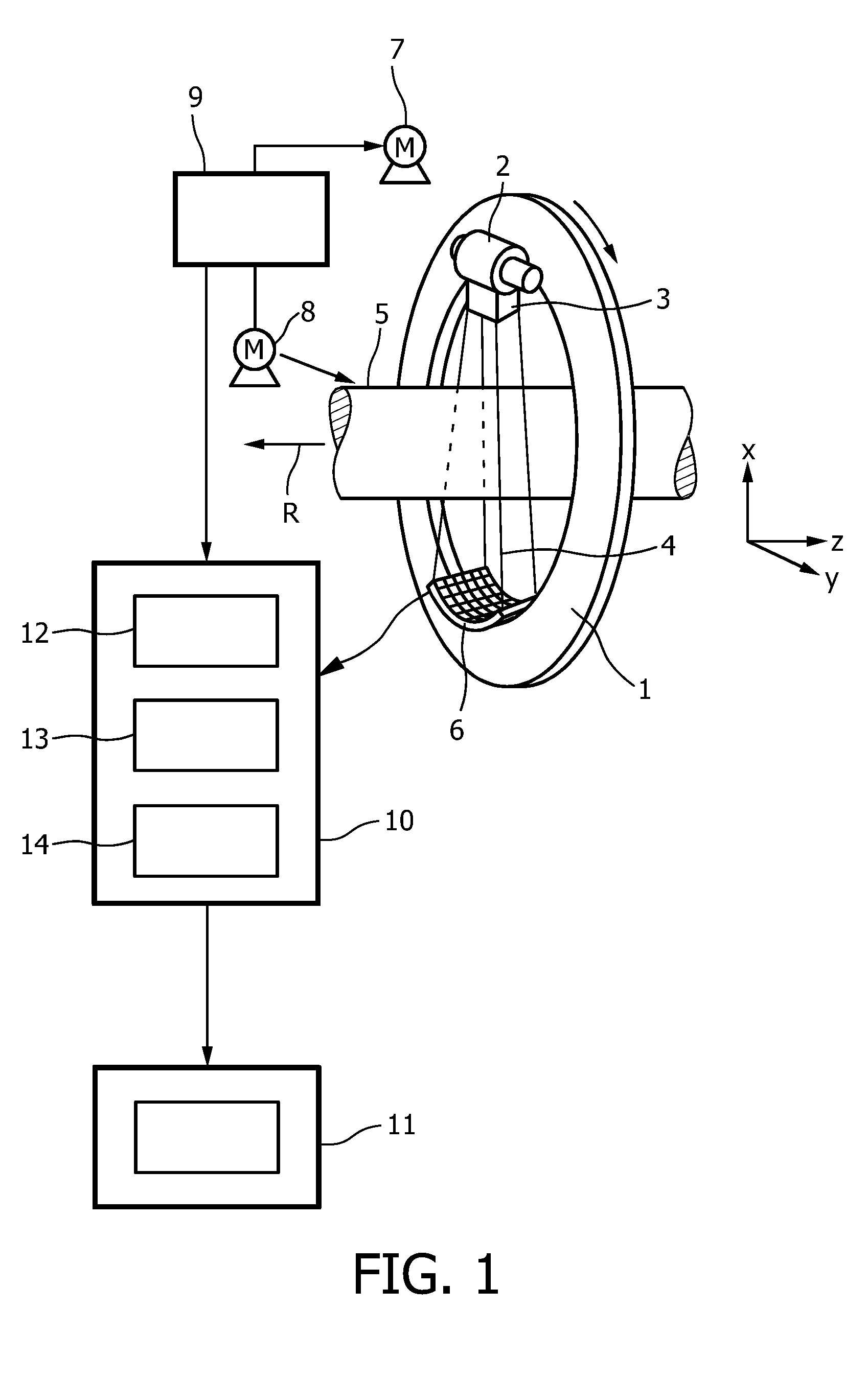
[0025]The CT imaging system shown in FIG. 1 includes a gantry 1 which is capable of rotating about an axis of rotation R which extends parallel to the z direction. A radiation source 2, for example an X-ray tube, is mounted on the gantry 1. The X-ray source is provided with a collimator device 3 which forms a conical radiation beam 4 from the radiation emitted by the X-ray source 2. In other embodiments, the collimator device 3 can be adapted for forming a radiation beam having another shape, for example, having a fan shape.

[0026]The radiation traverses an object (not shown), such as a patient, in a region of interest in a cylindrical examination zone 5. After having traversed the examination zone 5, the X-ray beam 4 is incident on an energy-resolving X-ray detector unit 6, in this embodiment a two-dimensional detector, which is mounted on the gantry 1. In another embodiment, the energy-resolving X-ray detector unit can be a one-dimensional detector.

[0027]Energy-resolving X-ray dete...


PUM

PropertyMeasurementUnit
energyaaaaaaaaaa
mean transit timeaaaaaaaaaa
energy-aaaaaaaaaa

Abstract

The invention relates to a CT imaging system for determining the flow of a substance within an object, wherein the CT imaging system comprises a polychromatic X-ray source and an energy-resolving X-ray detector for obtaining detection signals depending on the X-ray radiation after passing through the object. A calculation unit (12) determines a k-edge 5 component of the substance from the detection signals, and a reconstruction unit (13) reconstructs a time series of k-edge image from the determined k-edge component. A flow determination unit (14) determines flow values indicative for the flow within the object from the time series of k-edge images.

Description

FIELD OF THE INVENTION[0001]The present invention relates to a CT imaging system, a CT method and a computer program for determining the flow of a substance within an object. The invention relates further to a corresponding determination device, determination method and computer program for determining the flow of a substance within an object.BACKGROUND OF THE INVENTION[0002]Conventional CT imaging systems for determining the flow of a substance within an object use an X-ray source which emits X-ray radiation and a detection unit detecting detection signals depending on the x-ray radiation after passing through the object. The detection signals are used by a reconstruction unit to reconstruct times series of images of the object, wherein flow values indicative for the flow of the substance within the object are determined from the time series of images of the object. These flow values are for example the substance flow or the mean transit time through the object.[0003]By using these...

Claims


Application Information

Patent Timeline
Patent Type & Authority Applications(United States)
IPC IPC(8): H05G1/60G01N23/04
CPCA61B6/032A61B6/4241A61B6/481A61B6/507A61B6/504Y10S378/901A61B6/482
Inventor PROKSA, ROLAND
Owner KONINKLIJKE PHILIPS ELECTRONICS NV
Learn More