Identity labeling system for electrical cover plates

a technology for identification labels and electrical covers, applied in the field of electrical fixtures and cover plates, can solve the problems of not providing the appearance, unable to easily retrofit the type of labels to the existing switch plate cover, and only providing temporary and not attractive solutions, etc., and achieves the effect of convenient customization and readily available labels

Inactive Publication Date: 2010-03-11
ASKIN JOHN PATRICK +1
View PDF7 Cites 5 Cited by
  • Summary
  • Abstract
  • Description
  • Claims
  • Application Information

AI Technical Summary

Benefits of technology

[0005]Thus, it is the object of the present:invention to provide a light switch cover plate that is clearly labeled with a method that is both inexpensive and an attractive permanent solution.
[0009]The label cover plate is mounted to the typical electrical cover plate by simply removing one of the screws from the existing holes in the cover plate that secures the switch plate to the wall. The screw is then inserted through the identity plate and tightened to hold the label cover plate in position on the switch cover plate trapping the paper label between the label cover and the switch cover plate. A tab and groove combination at the ends of the covers ensures alignment and allows the use of multiple cover plates for multiple switch cover plates. This combination is an attractive permanent solution for identifying electrical connections.

Problems solved by technology

The above mentioned Dymo labels provide only a temporary and not a very attractive solution because they become unglued and scratch over time due to normal use.
They identify the switch but do not provide the appearance that most home and building owners would consider a permanent attractive solution to the problem.
This type of label is not easily retrofitted to existing switch plate cover because it takes knowledge of electricity to install.
This tag is not meant to be a permanent solution to the above mentioned problems.
It uses a separate back plate with a plastic cover and the tag is that is not easy for the end-user to customize.

Method used


Image

  • Identity labeling system for electrical cover plates
  • Identity labeling system for electrical cover plates
  • Identity labeling system for electrical cover plates

Examples


Embodiment Construction

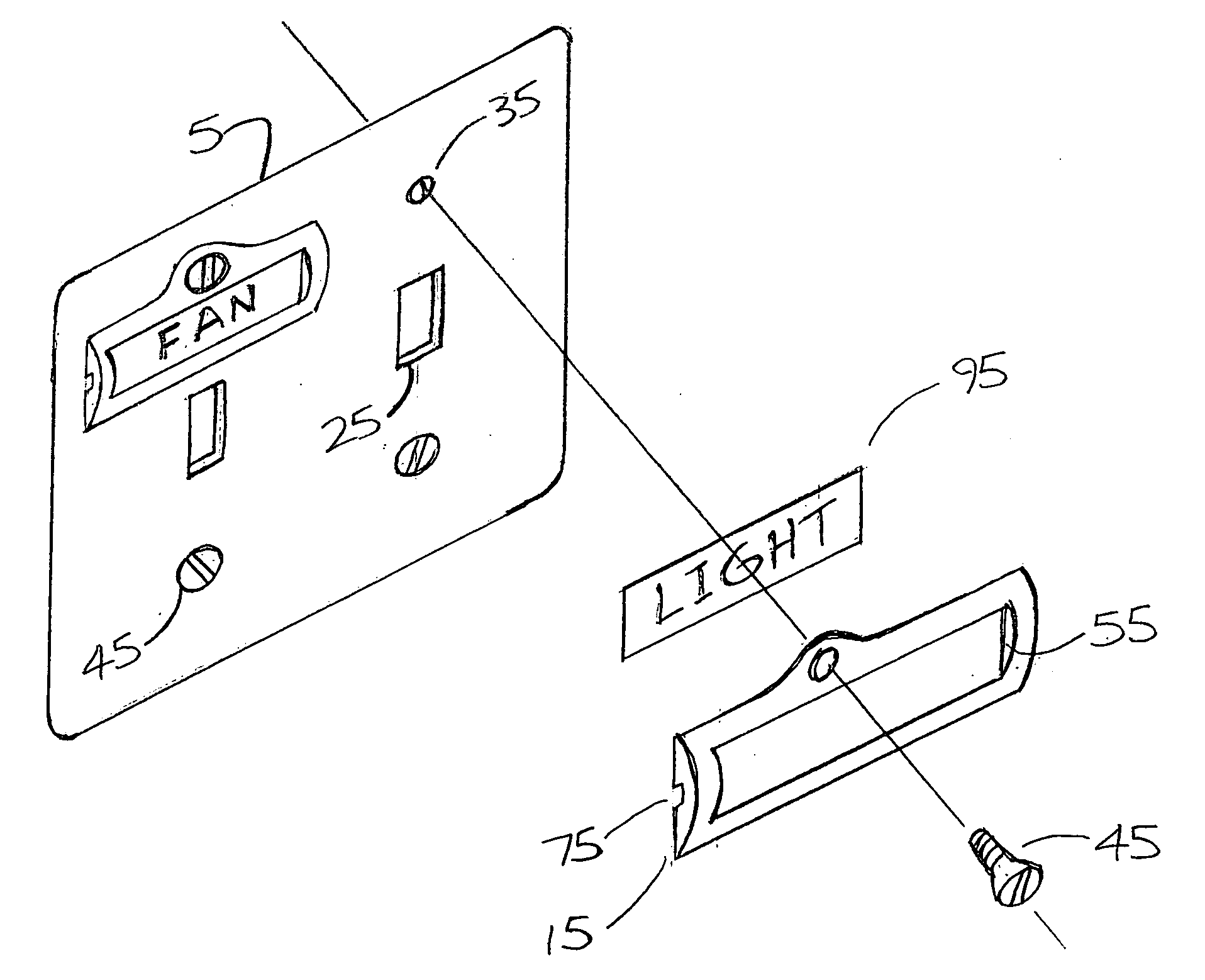
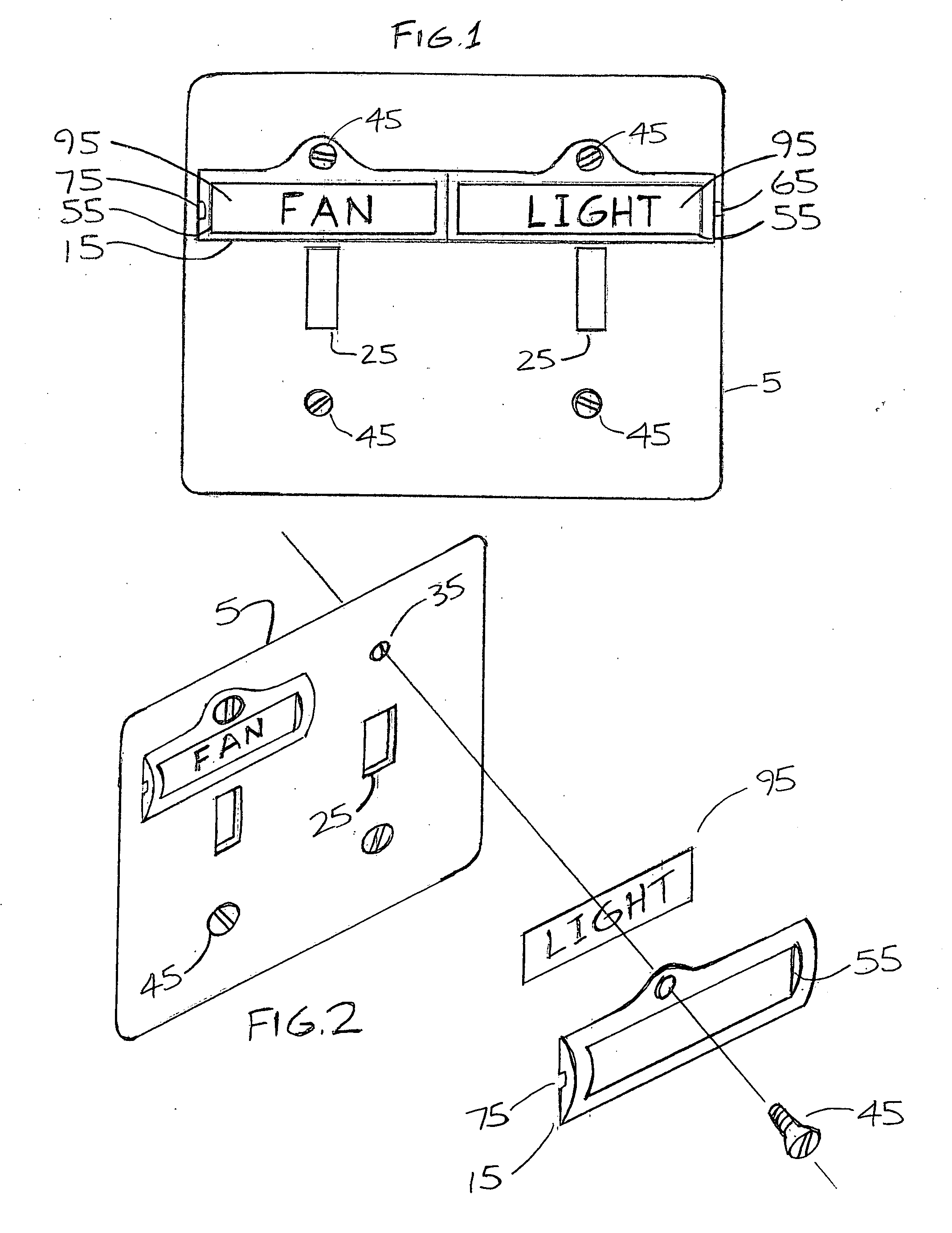
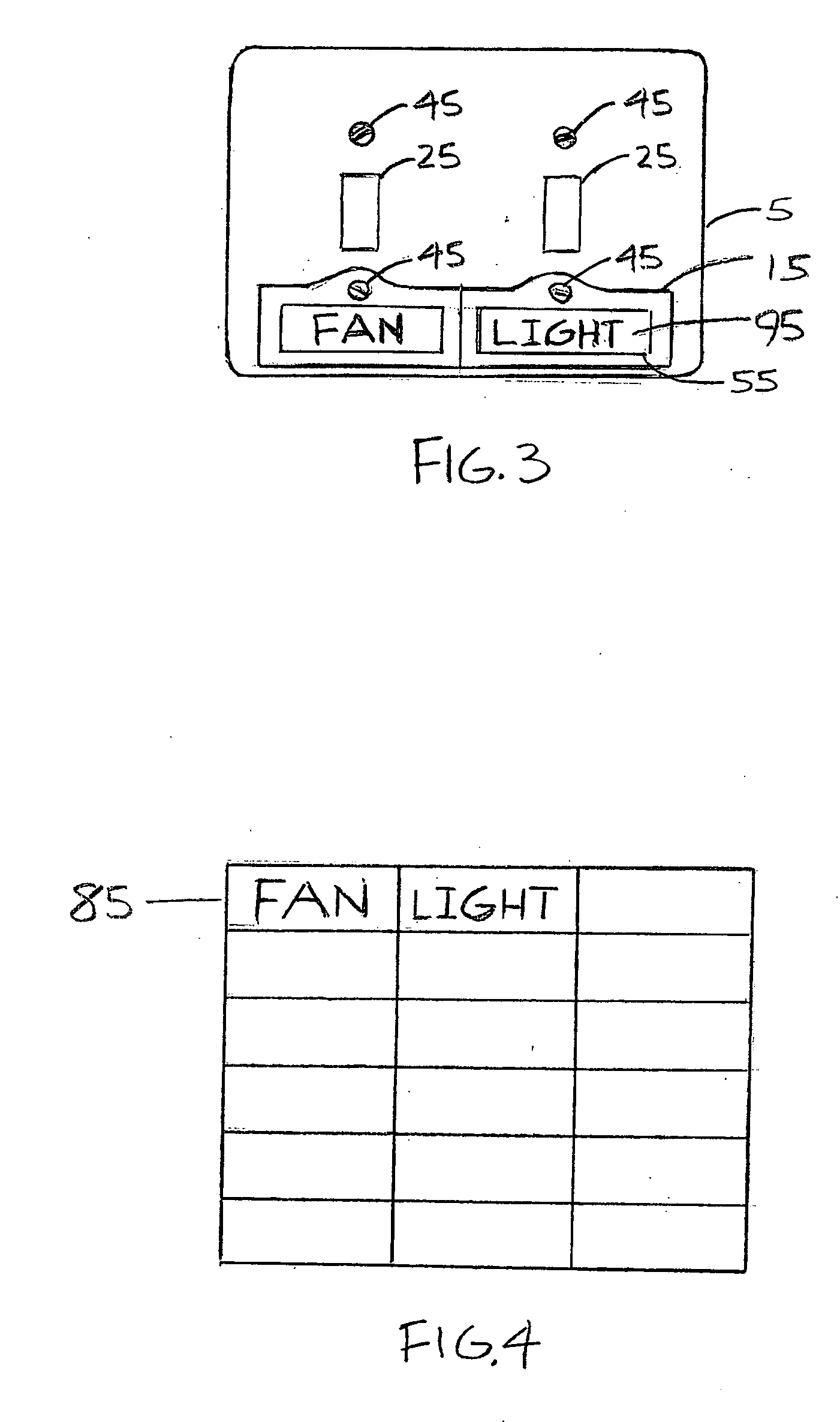
[0016]FIGS. 1-4 show a typical light switch cover plate (5) used in a manner that is common for covering typical light switches and their electrical connections. The switch plate cover includes openings (25) that expose the electrical switches or devices and holes (35) to accept screws (45) that secure the switch plate cover (5) onto the wall to cover electrical connections. The present invention (10) comprises a combination label (95) label cover plate (15) to identify the device that is controlled with the electricity that is supplied by the switch. It is attached to the switch cover plate (5) with the existing screw (45) that typically secures the switch cover plate (5) to the wall. The label cover (15) is made of a clear material. The label cover (15) includes a recess (55) in the back of the cover to hold the identity label (95) tabs (65) and grooves (75) to insure correct alignment during installation. The identity label (95) is a typical label that is used in offices to ident...


PUM


Abstract

Identity labeling system for a typical tight switch cover plate (5) used in a manner that is common for covering typical light switches and their electrical connections. The switch plate cover includes openings (25) that expose the electrical switches or devices and holes (35) to accept screws (45) that secure the switch plate cover onto the wall to cover the electrical connections. The improved method of labeling an existing switch plate comprises a label cover plate (15) attached to the switch cover plate (5) with the existing screw (45) that typically secures an existing switch cover plate to the wall. The cover plate is made of a clear material. The cover plate (15) includes a recess (55) in the back of the cover to hold the identity label (95) tabs (65) and grooves (75) to insure correct alignment during installation. The identity label (95) is a typical label that is used in offices to identify file folders. The labels come in perforated sheets (85) that can be imprinted by running them through a common computer printer to customize the labels to be used in any location to identify the switch.

Description

FIELD OF THE INVENTION[0001]This application relates generally to the field of electrical fixtures and cover plates and more specifically techniques and methods for labeling said fixtures to make the use of the fixtures more convenient.BACKGROUND OF THE INVENTION[0002]In both homes and commercial establishments, electrical cover plates are conventionally attached to the walls to cover the electrical connections of light switches. Use of this type of switch cover plate is well known in the art. Typically, the switch cover plate is secured to the receiving surface by screws. In an example of a light switch, as is well known, a light is typically turned on and off by flipping the light switch in the appropriate on or off position. It is common for several switches to be located in one general region covered by one larger multiple cover plate, such as a door or at the top of a stairway. In order to visually identify which light needs to be turned on or off by a certain light switch, a s...

Claims


Application Information

Patent Timeline
IPC IPC(8): G09F3/18
CPCH01H9/18G09F3/201
Inventor ASKIN, JOHN PATRICKSTEURER, STEVEN T.
Owner ASKIN JOHN PATRICK
Why Eureka
Try Eureka