
Driver Integrated Circuit Chip and Display Substrate of Flat Panel Display

a technology of integrated circuits and display substrates, applied in oscillator generators, pulse techniques, instruments, etc., can solve problems such as serious power drops, and achieve the effect of relieving serious power drops

Active Publication Date: 2010-03-04
AU OPTRONICS CORP
View PDF9 Cites 14 Cited by
  • Summary
  • Abstract
  • Description
  • Claims
  • Application Information

AI Technical Summary

Benefits of technology

[0012]The present invention relates to a driver IC chip can effectively avoid an output thereof to suffer from dramatic influence of serious power drop.
[0013]The present invention further relates to a display substrate of flat panel display, an output of a driver IC chip thereof can be effectively avoided to suffer from dramatic influence of serious power drop.
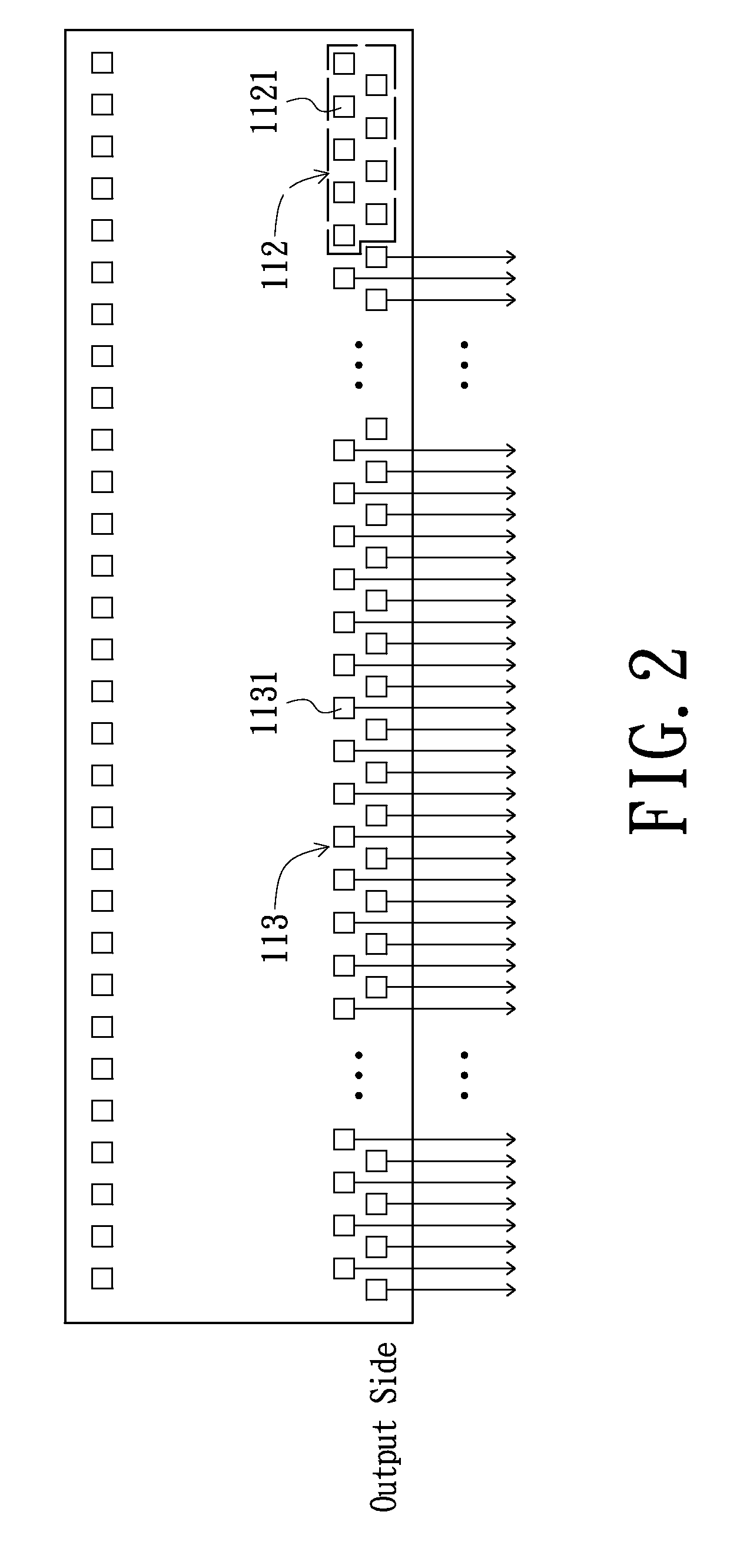
[0027]In the above-mentioned embodiments of the present invention, the opened second pin group which is formed at a side of the driver IC chip is located at at least one side of the first pin group, the excessive long transmission paths for signals in the prior art are removed off and thus the serious power drops can be relieved. Accordingly, the output of the driver IC chip can be effectively avoided to suffer from the dramatic influence of the serious power drops.

Problems solved by technology

However, since the second pin group 313 of each of the driver IC chips SD1˜SD8 and GD1˜GD3 is located at two opposite ends of the output side, which results in transmission paths of the power signals and / or the gamma voltage delivered to the sided output pins 3131 of the second pin groups 313 of the tailmost driver IC chips SD1, SD4, SD5, SD8 and GD3 of the groups of cascade connected driver IC chips are excessive long and thus the power drops are serious.

Method used


Image

  • Driver Integrated Circuit Chip and Display Substrate of Flat Panel Display
  • Driver Integrated Circuit Chip and Display Substrate of Flat Panel Display
  • Driver Integrated Circuit Chip and Display Substrate of Flat Panel Display

Examples


first embodiment

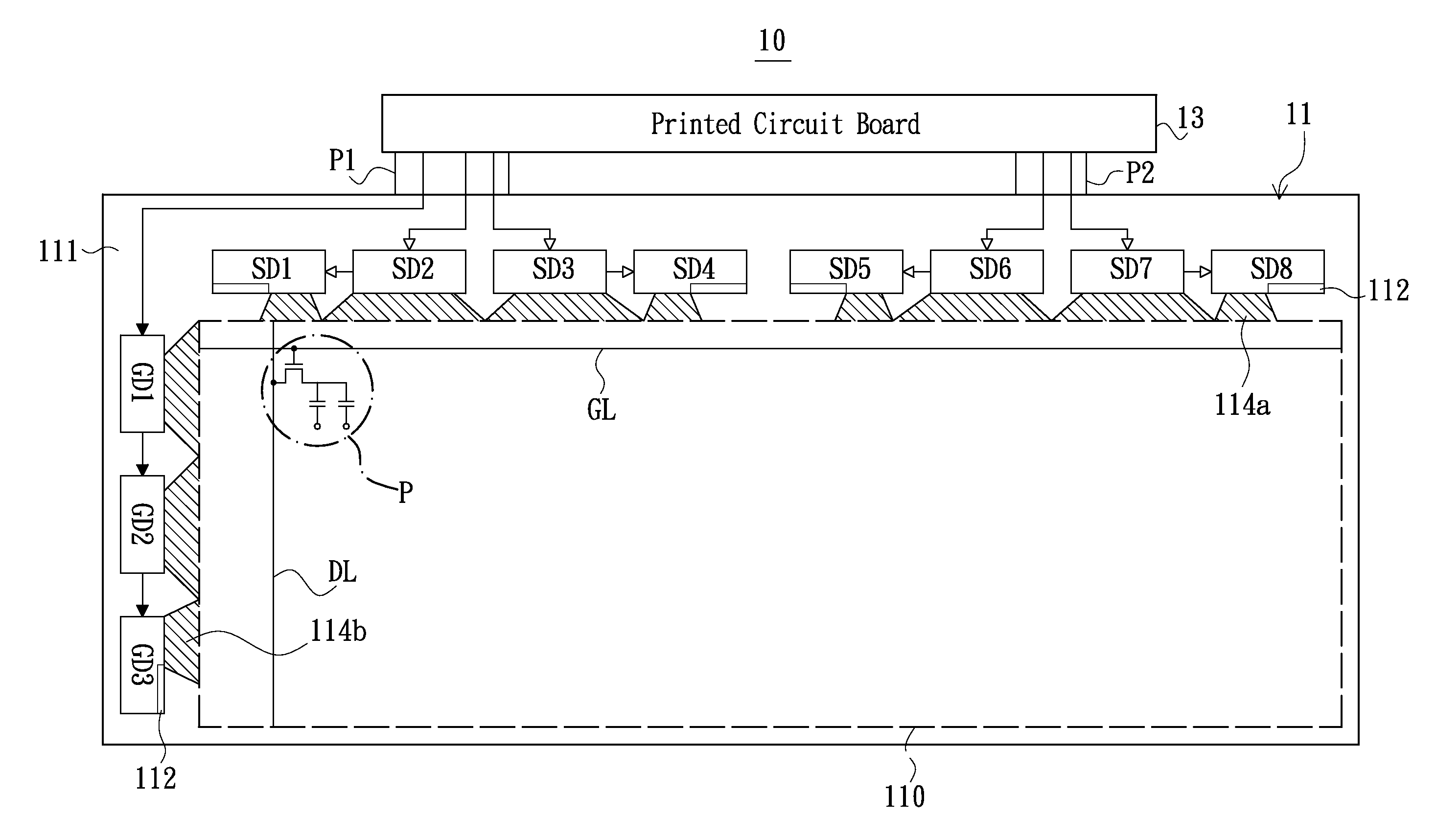
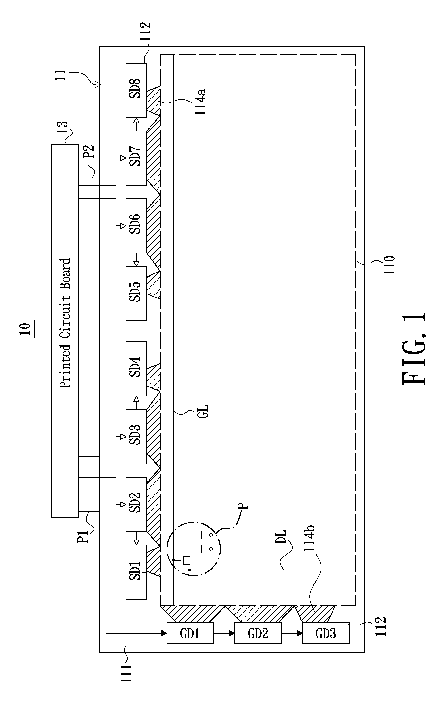
[0039]Referring to FIG. 1, a flat panel display 10 in accordance with the present invention includes a display substrate 11, a printed circuit board 13 and flexible printed circuit boards P1, P2. The flexible printed circuit boards P1, P2 are coupled between the display substrate 11 and the printed circuit board 13.

[0040]The display substrate 11 includes a display area 110 (as denoted by the dashed rectangle in FIG. 1), a peripheral area 111 located at sides of the display area 110, a plurality of source driver IC chips SD1˜SD8, a plurality of gate driver IC chips GD1˜GD3, a plurality of first fan-out wiring areas 114a and a plurality of second fan-out wiring areas 114b.

[0041]The display area 110 has a plurality of gate control lines GL (of which only one is shown in FIG. 1 for illustration purposes), a plurality of data lines DL (of which only one is shown in FIG. 1 for illustration purposes) and a plurality of display elements P (of which only one is shown in FIG. 1 for illustrat...

second embodiment

[0047]Referring to FIG. 4, a flat panel display 20 in accordance with the present invention is provided. The flat panel display 20 includes a display substrate 21, a printed circuit board 23 and flexible printed circuit boards P1, P2. The flexible printed circuit boards P1, P2 are electrically coupled between the display substrate 21 and the printed circuit board 23.

[0048]The display substrate 21 includes a display area 210 (as denoted by the dashed rectangle of FIG. 4), a peripheral area 211 located at sides of the display area 210, a plurality of source driver IC chips SD1˜SD8, a plurality of gate driver IC chips GD1˜GD3, a plurality of first fan-out wiring area 214a and a plurality of second fan-out wiring area 214b.

[0049]The display area 210 has a plurality of gate control lines GL (of which only one is shown in FIG. 4 for illustration purposes), a plurality of data lines DL (of which only one is shown in FIG. 4 for illustration purposes) and a plurality of display elements P (...


PUM


Abstract

A driver integrated circuit chip adapted to electrically couple with a fan-out wiring area includes a side and a plurality of output pins formed at the side. The output pins includes a first pin group and a second pin group. The first pin group is electrically coupled to the fan-out wiring area. The second pin group is located at at least one side of the first pin group and opened. The present invention also provides display substrates of flat panel display each adapted to electrically couple with a plurality of driver integrated circuit chips.

Description

CROSS-REFERENCE TO RELATED APPLICATIONS[0001]This application is based upon and claims the benefit of priority from the prior Taiwanese Patent Application No. 097132609, filed Aug. 26, 2008, the entire contents of which are incorporated herein by reference.BACKGROUND[0002]1. Technical Field[0003]The present invention generally relates to flat panel display field and, particularly, to a driver integrated circuit (IC) chip and display substrates of flat panel display adapted to electrically couple with a plurality of driver IC chips.[0004]2. Description of the Related Art[0005]Flat panel displays such as a liquid crystal display (LCD) and a plasma display have the advantages of high image quality, small size, light weight and a broad application range, and thus are widely applied on consumer electronic products such as a mobile phone, a notebook computer, a desktop display and a television, and have gradually replaced the traditional cathode ray tube (CRT) displays as the main trend i...

Claims


Application Information

Patent Timeline
Patent Type & Authority Applications(United States)
IPC IPC(8): G09G3/36H03K3/00
CPCG09G3/3685G09G2320/0223G09G2300/0426G09G2300/0408
Inventor CHUNG, CHUN-FANHSU, SHENG-KAI
Owner AU OPTRONICS CORP
Learn More