RFID textile label

a textile label and RFID technology, applied in the field of RFID textile labels, can solve the problems of inconvenient use of RFID labels, inability to meet the needs of short range transponders, and the way of use is rather less suitable for textile labels

Inactive Publication Date: 2010-03-04
TEXTILMA AG
View PDF11 Cites 12 Cited by
  • Summary
  • Abstract
  • Description
  • Claims
  • Application Information

AI Technical Summary

Benefits of technology

[0008]Permanently connecting the RFID chip to the sides of the antenna loop, provides a particularly simple solution.
[0009]However, it is also possible to arrange the RFID chip at the ends of a conductor loop on an auxiliary carrier, at least sections of said conductor loop running parallel to the antenna loop at a short distance from the latter and said conductor loop being inductively coupled to said antenna loop. It is also possible to arrange the RFID chip at the ends of a conductor loop on an auxiliary carrier, the conductor loop overlapping or crossing the antenna at at least two places and partially running parallel to the antenna at a distance from the latter and being inductively coupled to the antenna.
[0011]The textile carrier is in the form of a textile sheet-like structure to which the antenna is fastened. For this purpose, the antenna may be applied to the textile sheet-like structure using a sewing or stitching method, or may be printed on in the form of an electrically conductive ink. However, it is more advantageous if the antenna is incorporated in the sheet-like structure, this being able to be effected, for example, by knitting it into knitwear. However, the embodiment according to which the textile sheet-like structure is a woven fabric, into which the antenna is woven during the production of the woven fabric on a weaving machine, is particularly advantageous.

Problems solved by technology

Together with the RFID chip, such E-field antennas form a transponder which is not suitable for short ranges.
These ways appear to be rather less suitable for use in textile labels.

Method used


Image

  • RFID textile label
  • RFID textile label
  • RFID textile label

Examples


Embodiment Construction

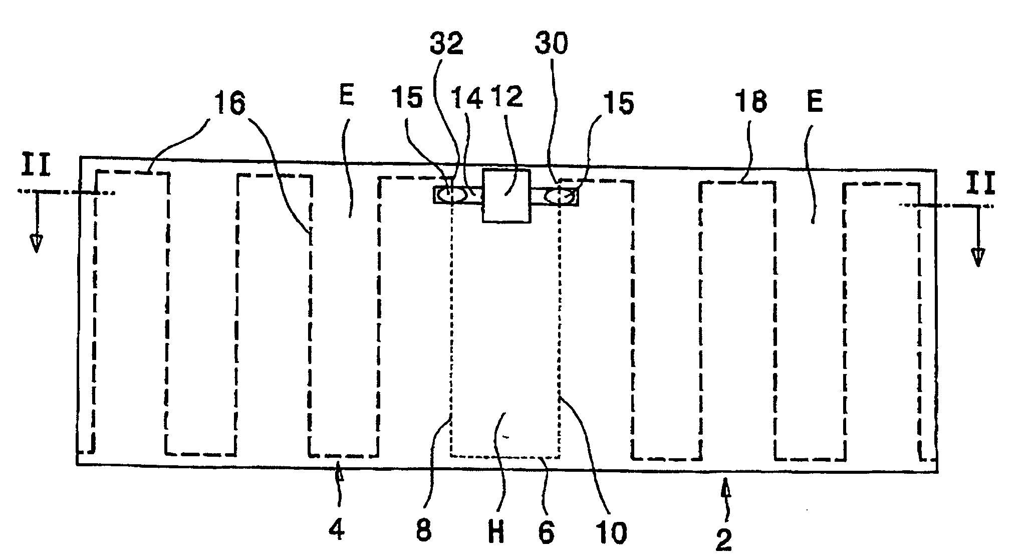
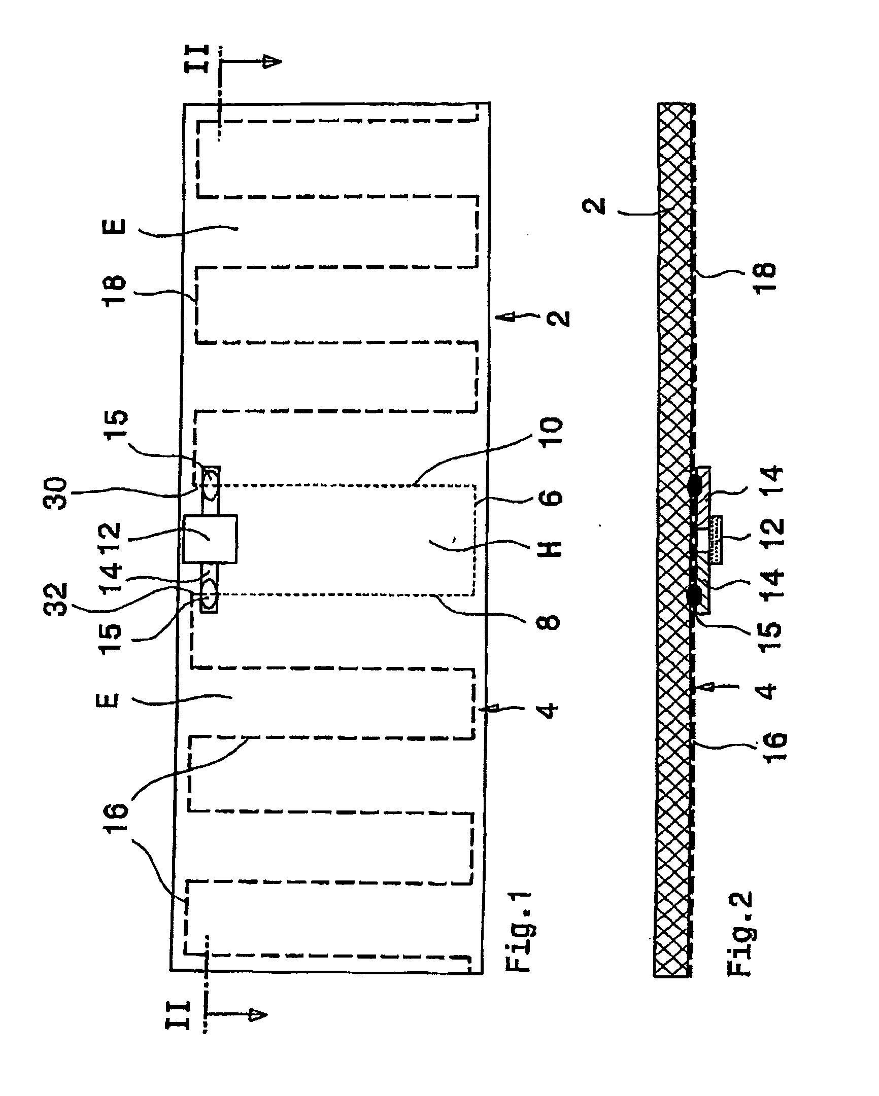
[0021]FIGS. 1 and 2 show a first exemplary embodiment of an RFID textile label having a textile carrier 2 made of a woven fabric into which an open antenna 4 is woven in meandering fashion. A loop 6 of the antenna, to the sides 8, 10 of which an RFID chip 12 is fastened by means of connection bases 14, is singled out in the central region, that is to say at half the length of the antenna. The connection bases 14 are connected 15 to the antenna 4 by means of welding, soldering or by means of an electrically conductive adhesive, for example. The antenna loop 6 forms an H-field antenna for close range and the antenna sections 16, 18 which are outside the antenna loop 6 are used as an E-field antenna for long range.

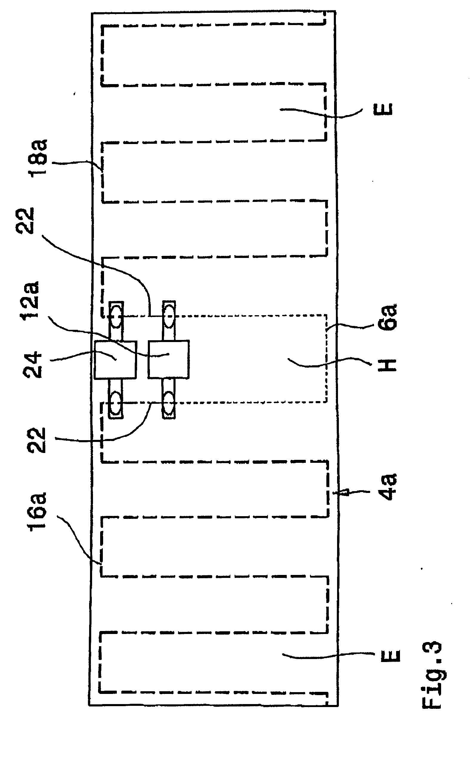
[0022]FIG. 3 shows a further RFID textile label which is constructed, in principle, like that in FIGS. 1 and 2 but the antenna loop 6a of the antenna 4a is separated from the antenna sections 16a, 18a by means of interruptions 20, 22. The RFID chip 24 is connected to the ante...


PUM


Abstract

The invention relates to an RFID textile label, having an open antenna disposed on a carrier, wherein the antenna is connected to an RFID chip at the center region. In order to make the RFID textile label suitable both for long range and close range, the antenna comprises a loop in the center region, the RFID chip being connected either directly or indirectly to the shoulders of this loop, wherein the antenna loop equipped with the RFID chip serves as an H field antenna, and the antenna sections disposed outside of the antenna loop serve as an E field antenna.

Description

[0001]This application claims priority of PCT application PCT / CH2007 / 000443 having a priority date of Sep. 18, 2006, the disclosure of which is incorporated herein by reference.TECHNICAL FIELD[0002]The invention relates to an RFID textile label.BACKGROUND OF THE INVENTION[0003]WO02 / 093524 A discloses an RFID textile label having an open antenna which is arranged on a carrier and is connected to an RFID chip. This antenna is in the form of a dipole antenna which is subdivided into two halves by the RFID chip and is used as an E-field antenna which is designed for an operating frequency in the UHF or microwave band. Together with the RFID chip, such E-field antennas form a transponder which is not suitable for short ranges.[0004]U.S. 2006 / 0043198 A1 describes different ways of capacitively and inductively coupling an RFID chip to a dipole antenna (E-field antenna) and to a loop antenna (H-field antenna). These ways appear to be rather less suitable for use in textile labels.SUMMARY OF...

Claims


Application Information

Patent Timeline
Patent Type & Authority Applications(United States)
IPC IPC(8): G06K19/07
CPCD06H1/04G06K7/10178G08B13/2445G06K19/07749G06K19/027G06K19/077G08B13/24G09F3/02
Inventor SPEICH, FRANCISCO
Owner TEXTILMA AG
Why Eureka
Try Eureka