
Method and arrangement for secure user authentication based on a biometric data detection device

a biometric data and user authentication technology, applied in digital transmission, wireless communication, instruments, etc., can solve problems such as unsatisfactory solutions, and achieve the effect of convenient portability

Inactive Publication Date: 2010-02-25
TELECOM ITALIA SPA
View PDF14 Cites 84 Cited by
  • Summary
  • Abstract
  • Description
  • Claims
  • Application Information

AI Technical Summary

Benefits of technology

The invention provides a terminal that has a special card called a smartcard which stores unique physical features (biometric) about its users. This terminal also includes a sensor that detects these biometric features. The two can communicate with each other over a wireless network to verify who they are. This makes it harder for people to manipulate or steal the stored biometric information. Furthermore, because the verification process doesn't rely on any specific equipment, it works well across different devices and platforms.

Problems solved by technology

This patent discusses how users can make their own computer terminals and mobile phones safer from unauthorized access. One common approach is through the use of user id/password pairs or smart cards, but they have limitations when trying to prevent all types of attacks. To address this issue, companies like Apple Inc. have introduced biometric authentication methods, which rely on unique physical or behavioral traits to verify who the user really is. However, current technology still has its drawbacks, including potential vulnerabilities related to privacy concerns.

Method used


Image

  • Method and arrangement for secure user authentication based on a biometric data detection device
  • Method and arrangement for secure user authentication based on a biometric data detection device
  • Method and arrangement for secure user authentication based on a biometric data detection device

Examples


first embodiment

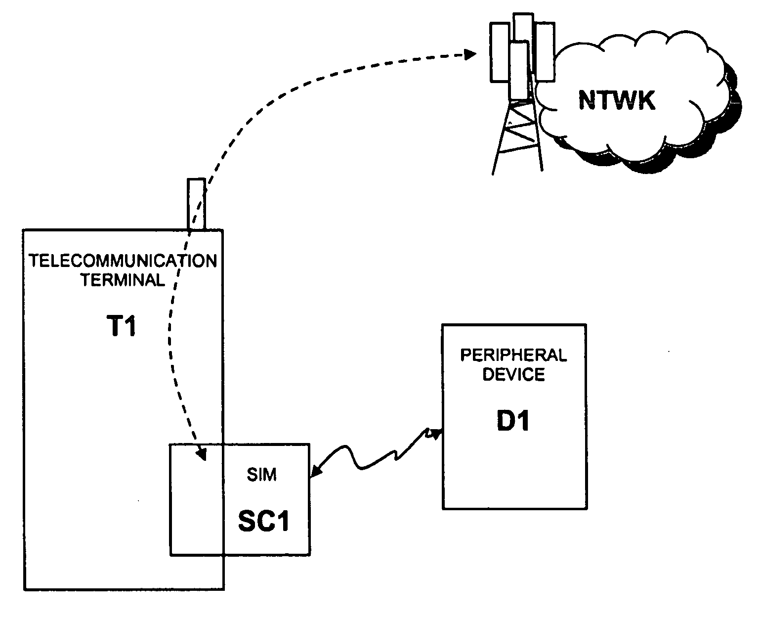
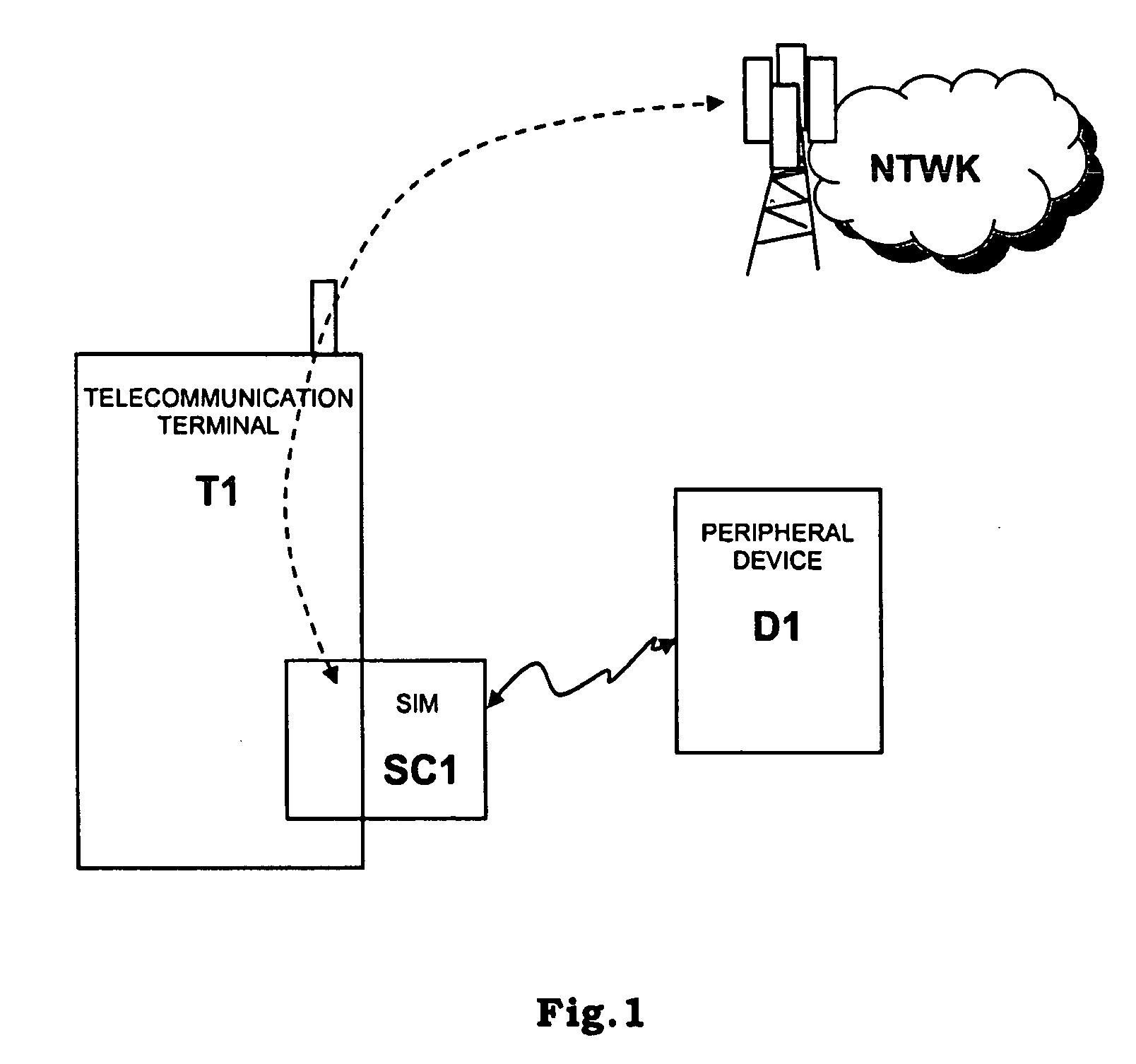
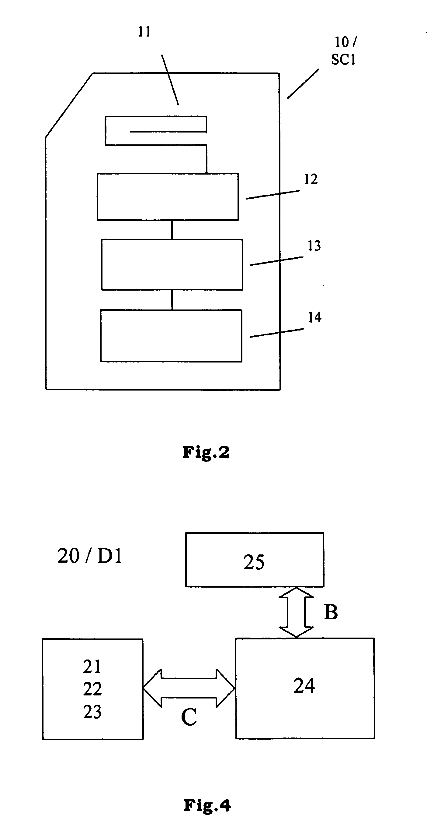
[0075]According to a first embodiment of the present invention (that may be implemented through the hardware architectures shown in FIG. 1, FIG. 2 and FIG. 4), device D1 receives from smartcard SC1 a reference fingerprint template and matches it with a fingerprint template deriving from the fingerprint data detected by its fingerprint sensor; the result of this matching is transmitted by device D1 to smartcard SC1.

[0076]The authentication procedure according to this first embodiment is shown in FIG. 5 and FIG. 6; FIG. 5 relates to the steps carried out in the smartcard, in particular by a biometric management application, while FIG. 6 relates to the steps carried out in the biometric device.

[0077]The flowchart of FIG. 5 relates to steps carried out by the biometric management application as a consequence of a request of biometric authentication by a service management applet running in the smartcard; FIG. 3 can be considered for clarification.

[0078]The steps of the flowchart of FIG....

second embodiment

[0111]According to a second embodiment of the present invention (that may be implemented through the hardware architectures shown in FIG. 1, FIG. 2 and FIG. 4), smartcard SC1 receives from device D1 a detected fingerprint template (deriving from the fingerprint data detected by the fingerprint sensor of device D1) and makes a match between a reference fingerprint template (stored locally) and the detected fingerprint template.

[0112]The authentication procedure according to this second embodiment is shown in FIG. 7 and FIG. 8; FIG. 7 relates to the steps carried out in the smartcard, in particular by a biometric management application, while FIG. 8 relates to the steps carried out in the biometric device.

[0113]The flowchart of FIG. 7 relates to steps carried out by the biometric management application as a consequence of a request of biometric authentication by a service management applet running in the smartcard; FIG. 3 can be considered for clarification.

[0114]The steps of the flow...


PUM


Abstract

An arrangement for secure user authentication includes a computer or telecommunication terminal with a smartcard and a device. The smartcard is adapted to securely store biometric information relating to at least one user and the device is adapted to detect biometric data of users. The smartcard and the device include a radio interface for communicating together and a module for exchanging biometric information between each other. In this way, tampering of the transferred biometric information is difficult. In order to increase the security, one or more of the following measures may be used: a secure communication channel between the device and the smartcard, a direct (preferably short range) communication channel between the device and the smartcard and encryption and decryption of biometric information transferred between the device and the smartcard.

Description


Claims


Application Information

Patent Timeline
Owner TELECOM ITALIA SPA
Learn More