[0005]Embodiments of the present invention advantageously provide an oil sump having an oil filter, which no longer has the disadvantages described above and / or in particular to disclose an oil sump, preferably made of
metal or plastic, in which the oil filter is integratable permanently, the number of the required components being reduced simultaneously, the
assembly being made easier, the costs for production and installation being lowered, undesired disadvantageous technical effects being reduced, and the filter being easily replaceable as needed and thus being able to be situated so it can be separated in the oil sump.
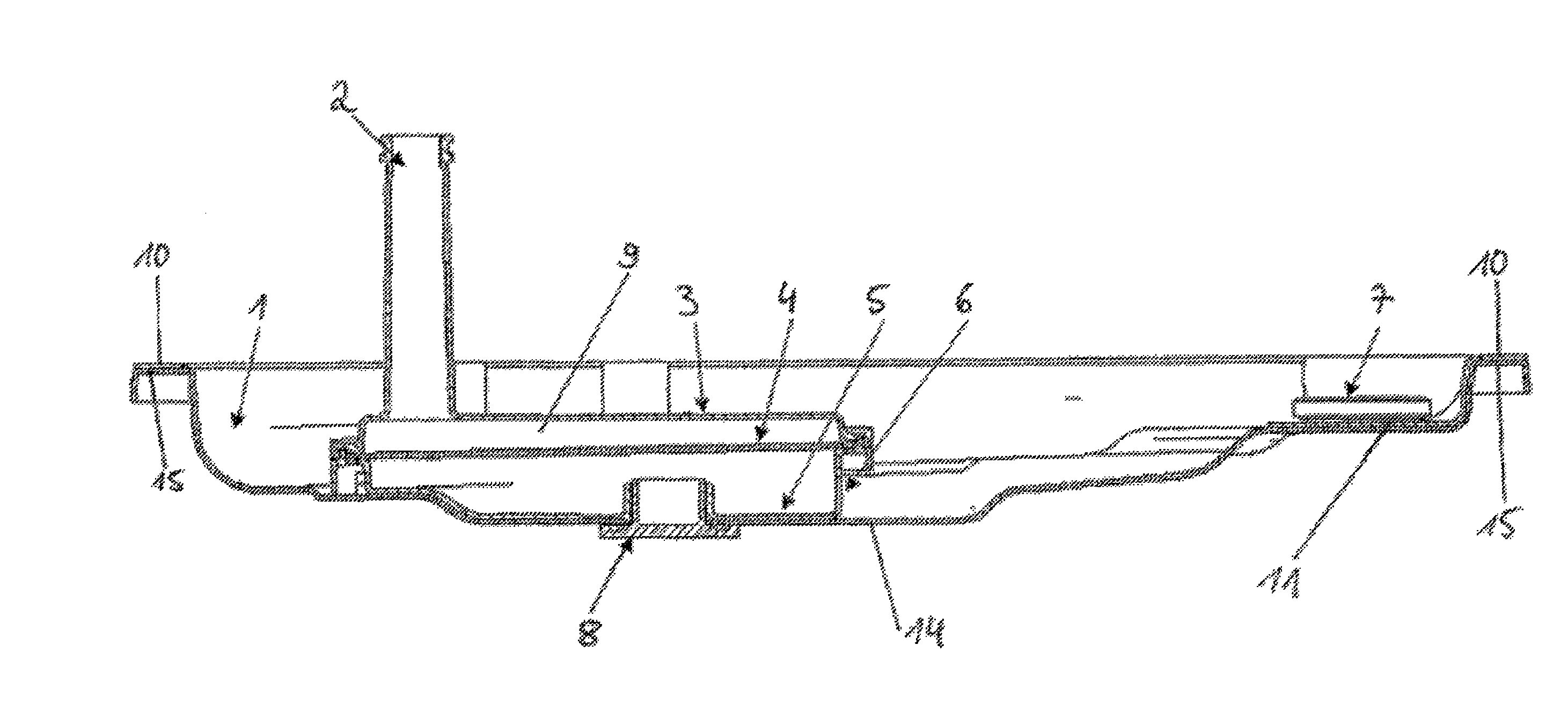
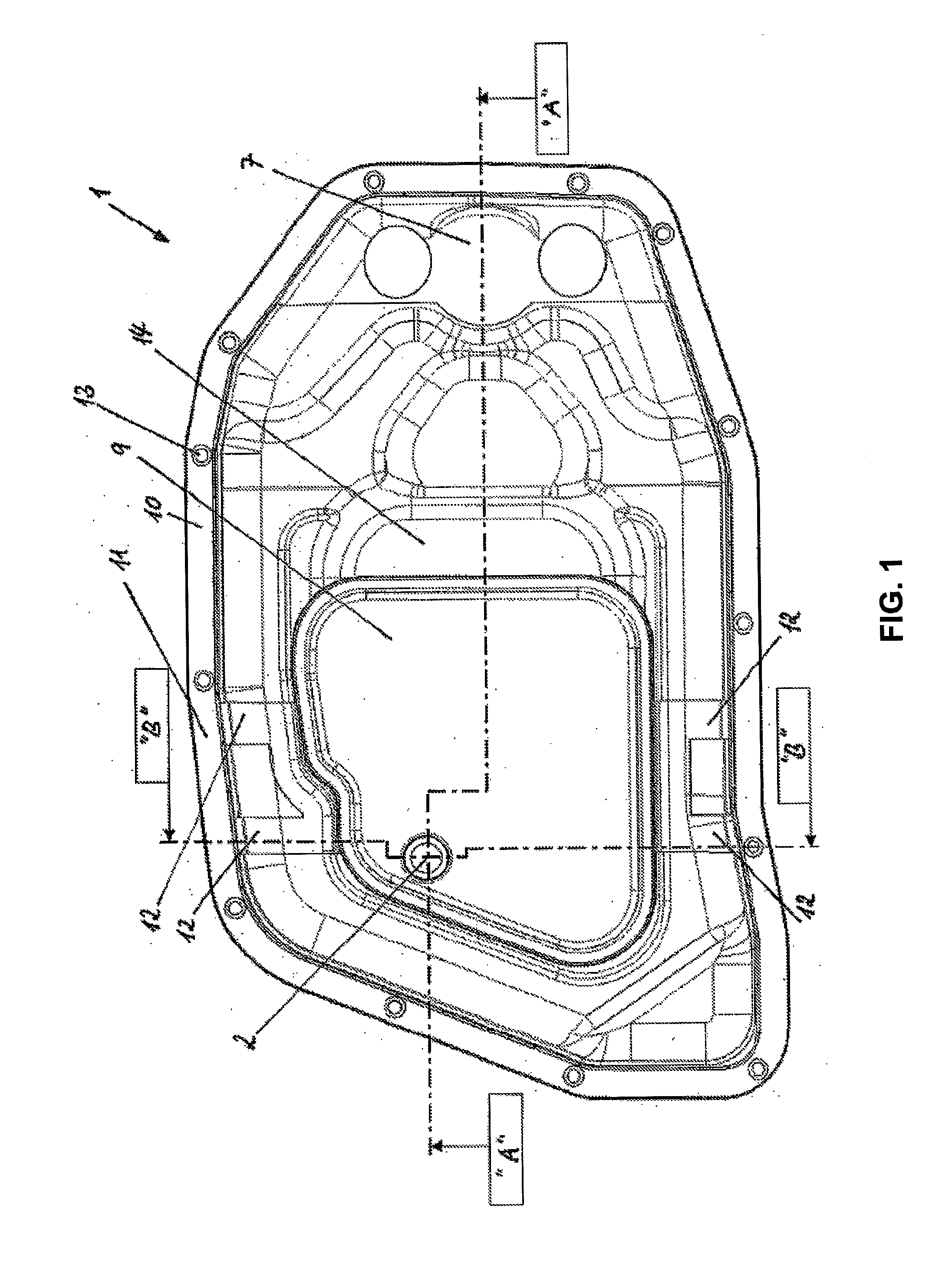
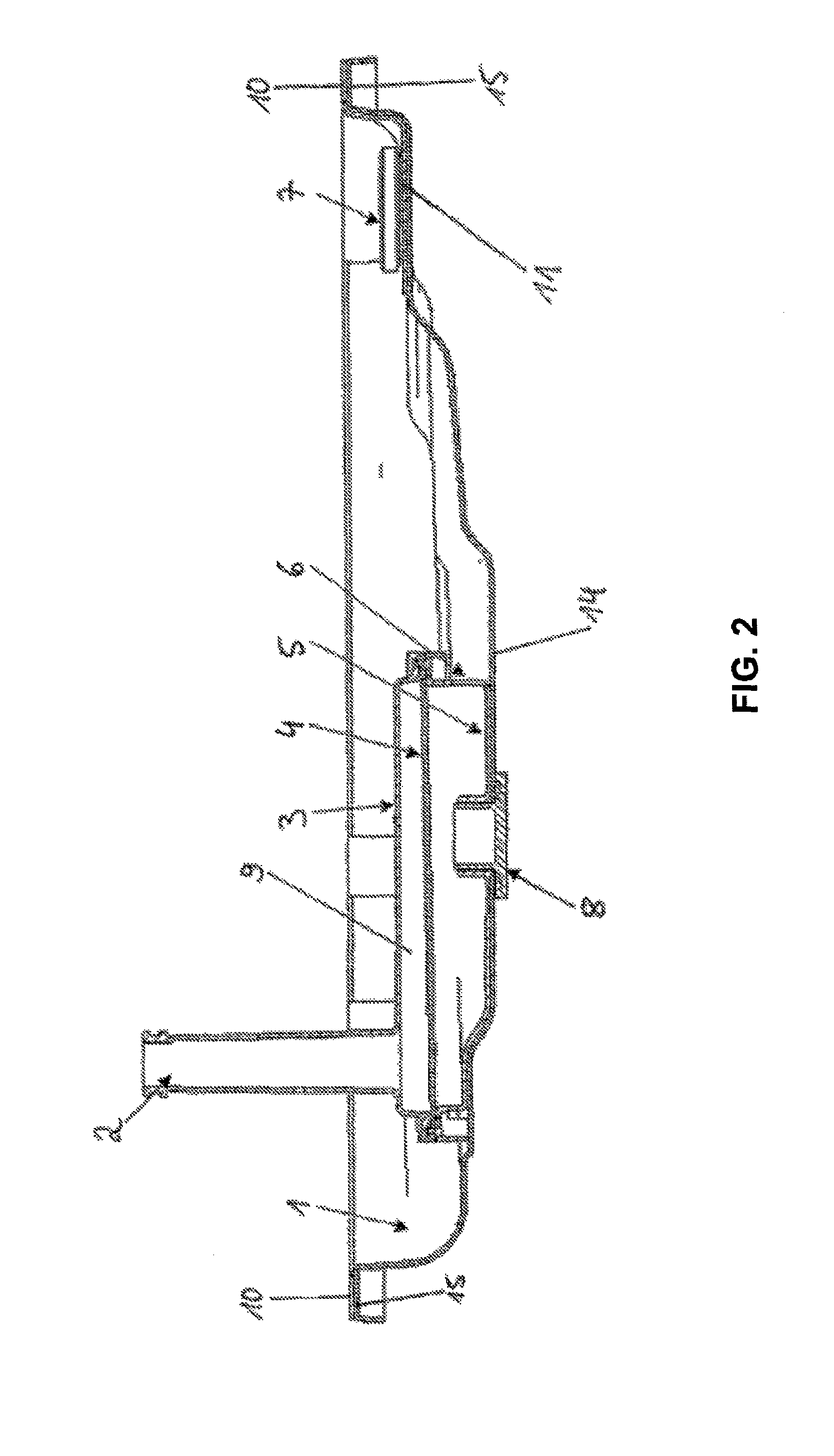
[0006]The oil sump is preferably entirely or partially made of plastic or metal, and is suitable in particular for engines or transmissions. The oil sump comprises a filter housing and an oil drain opening in the floor area of the oil sump. The filter housing comprises a filter housing top shell, a filter housing bottom shell, a filter medium, a filter inlet, and a filter outlet. The construction of such a filter housing is fundamentally known from the prior art. The oil drain opening in the floor area of the oil sump is implemented in such a way that it is closable using an oil drain screw having external thread which comes from the oil sump outer side. The oil sump has a carrier unit having a frame, on which the filter housing is fastened and which is used as a seal upon fastening of the oil sump on the associated unit, in particular on an engine block or a transmission unit. This fastening may be performed directly or indirectly, and it may be removable or non-removable. The carrier unit may be implemented in one piece or multiple pieces. The carrier unit may be produced from a single material or from various materials, and this is also true for its various parts. Because the filter housing is fastened on the carrier unit, the filter housing may be removed together with the carrier unit from the oil sump in the event of a possible filter change. The use of the carrier unit thus makes access to the filter housing easier. The frame of the carrier unit is used as a seal upon fastening of the oil sump on the associated unit, such as an engine block or a transmission unit. This presumes that, on the one hand, the material of the frame of the carrier unit is selected accordingly, and the dimensions of the frame are adapted to the oil sump and / or its external dimensions, in particular the outer edge, so that the sealing effect may be achieved in its entirety as much as possible on the basis of the carrier unit when the oil sump is fastened on the associated unit. The integrated implementation of carrier unit having a frame, which has seal properties, and having the filter housing has the
advantage that the number of required individual parts is reduced further. It is no longer necessary in particular to use a separate seal for fastening the oil sump on its associated unit. The oil sump is preferably fastened on its associated functional unit by screwing.
[0011]According to a further preferred embodiment of the invention, the carrier unit has one web or multiple webs, via which the filter housing is connected to the carrier frame. The filter housing is frequently located in a central area of the oil sump and not directly adjoining a side wall of the oil sump. In order to produce a connection between the filter housing and the carrier unit and / or the frame of the carrier unit, connection elements are provided from the filter housing up to the frame of the carrier unit. These elements are preferably implemented in the form of webs. These are comparatively narrow connection elements which may be provided individually, in pairs, or in multiples. The dimensions of the webs and their numbers may be adapted to the required stability, vibration behavior, etc. of the entire oil sump unit. The filter housing is preferably connected on at least two positions to the frame of the carrier unit using one or more webs in each case. The position of these connection elements and / or webs is preferably selected so that the distance to the frame is low, on the one hand, and the connection points are preferably opposite to one another, on the other hand. This allows the greatest possible stability. The webs may form the connection between frame and filter housing freely traversing the oil sump, according to a preferred embodiment of the invention, the webs are designed so that they cling to the floor of the oil sump in the connected state. This allows an especially good and secure and, in addition, space-saving fastening.
[0012]According to a further preferred embodiment of the invention, the oil sump has a
magnet on which the carrier unit is fastened or fastenable. Such a
magnet is fundamentally known from the prior art and is used for collecting metal parts in the oil sump, such as small metal particles, which may occur because of wear phenomena in the functional unit associated with the oil sump. The
magnet may be fastened on the carrier unit in greatly varying ways. In particular, it may be removably fastened on the carrier unit. Upon a replacement of the magnet, it may thus be easily removed together with the entire carrier unit from the oil sump and replaced as needed on the carrier unit. The magnet may, for example, be screwed down, glued on, or also simply held by magnetic forces and / or appropriate shaping, e.g., depressing the carrier unit at the point provided for the magnet, on its place in the carrier unit.
[0015]In a further preferred embodiment of the invention, the filter housing bottom shell is formed by a floor area of the oil sump, and the filter housing top shell comprises an internal thread which is implemented to receive the external thread of the oil drain screw. In this embodiment, a separate filter housing bottom shell is thus not necessary, because this function is achieved by a subarea of the oil sump floor. The module, which is to be fastened on the oil sump and is open toward one side, thus comprises at least the filter housing top shell (and optionally also the filter medium). Correspondingly, the internal thread which is necessary to receive the external thread of the oil drain screw is situated on the filter housing top shell. In order to make the engagement of the external thread of the oil drain screw in the internal thread on the filter housing top shell side easier, it is preferably implemented in a way protruding from the inner surface of the filter housing top shell and pointing in the direction toward the oil sump floor. Especially preferably, the internal thread and / or the part of the filter housing top shell forming the internal thread protrude far enough in the direction of the oil sump floor that, in the installed state, this part of the filter housing top shell stands on the oil sump floor and / or is in contact therewith. The filter housing top shell is fastened especially well on the oil sump floor in this way.


